|
Status Registers
|
|
|
|
|
Reference (hex)
|
Purpose
|
Contents
|
|---|---|---|
|
4F801
|
Length of status block (words)
|
12 decimal
|
|
4F802
|
I/O module quantity of input bytes
|
Module dependent
|
|
4F803
|
I/O module quantity of output bytes
|
Module dependent
|
|
4F804
|
I/O module ID number
|
Module dependent
|
|
4F805
|
I/O module revision number
|
Format: XRwhere:X = upper 4 bits, always 0000R = lower 12 bits, defining the revision as 3 hex characters.Example: 100 hex = Rev. 1.00 200 hex = Rev. 2.00
|
|
4F806
|
ASCII header block length (words)
|
Module dependent
|
|
4F807
|
Last node address to communicate
|
1...64 decimal
|
|
4F808
|
Remaining ownership reservation time
|
30...6000 decimal, in units of 10 ms (300 ms...60 s)
|
|
4F809
|
Remaining outputs holdup time
|
30...6000 decimal, in units of 10 ms (300 ms...60 s)
|
|
4F80A
|
I/O module health
|
8000 hex = healthy0000 hex = not healthy
|
|
4F80B
|
I/O module last error value
|
Module dependent
|
|
4F80B
|
I/O module error counter
|
Error count 0000...FFFF hex
|
|
4FC01+Byte Offset
|
ASCIICharacters
|
Meaning
|
|---|---|---|
|
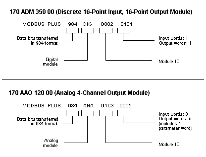
0...10
|
MODBUS PLUS
|
Modbus Plus network device
|
|
11
|
20 hex (32 decimal)
|
space
|
|
12
|
20 hex (32 decimal)
|
space
|
|
13 14 15
|
IEC
|
IEC data mode (Data bit order per IEC standard)
|
|
16
|
20 hex (32 decimal)
|
space
|
|
17 18 19
|
DIGEXPANA
|
Digital module (ID range: XX00...XX7F hex)Expert module (ID range: XX80...XXBF hex)Analog module (ID range: XXC0...XXFE hex)
|
|
20 21
|
HHLL
|
Module ID code(HH = high byte, LL = low byte)
|
|
22 23
|
I I OO
|
Module I/O words(I I = input words, OO = output words)
|
|
24...63
|
--
|
Reserved
|
