|
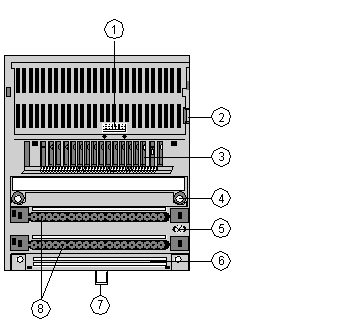
Front Panel Components
|
|
|
Original instructions
|

|
Label
|
Description
|
|---|---|
|
1
|
internal interface (ATI) connector
|
|
2
|
locking and ground contact for the adapter
|
|
3
|
LED status display
|
|
4
|
mounting holes for panel mount
|
|
5
|
grounding screw
|
|
6
|
busbar mounting slot
|
|
7
|
locking tab for DIN rail mount
|
|
8
|
sockets for the terminal connectors
|

|
Indicator
|
Condition
|
Message
|
|---|---|---|
|
Ready
|
Green
|
Module is ready to communicate. Operating voltage for internal logic (5 V) is present.
|
|
Off
|
Module not ready.
|
|
|
FUSE 1
|
Green
|
Output voltage of outputs 1 ... 4 (one common output voltage for group 1) present and fuse 1 is OK.
|
|
Off
|
Output voltage of outputs 1 ... 4 (one common output voltage for group 1) is not present and/or fuse 1 is defective
|
|
|
FUSE 2
|
Green
|
Output voltage of outputs 5 ... 8 (one common output voltage for group 2) present and fuse 1 is OK.
|
|
Off
|
Output voltage of outputs 5 ... 8 (one common output voltage for group 2) is not present and/or fuse 1 is defective
|
|
|
Upper row IN
1...10
|
Green
|
Input status (an LED per input);
Input point active, i.e., input carries a 1 signal (logically ON)
|
|
Off
|
Input status (an LED per input);
Input point inactive, i.e., input carries a 0 signal (logically OFF)
|
|
|
Middle row OUT
1,3 ,5 ,7 , 9, 11, 13, 15
|
Green
|
Output status (an LED per output);
Output point active, i.e., output carries a 1 signal (logically ON)
|
|
Off
|
Output status (an LED per output)
Output point inactive, i.e., output carries a 0 signal (logically OFF)
|