The 170 ADO 540 50 TSX Momentum I/O base supports 16 discrete outputs. This section contains information about the mapping of the I/O data into output words.
The I/O base may be mapped as one output word, or as 16 discrete output points.
In order to correctly field wire the outputs and map the output data, you need to know which type of Momentum adapter is mounted on the base.
Adapters may be either IEC compliant or 984 Ladder Logic compliant.
|
|
IEC Compliant
|
984 Ladder Logic Compliant
|
|
Momentum Processor Adapters
|
All
|
None
|
|
Momentum Communication Adapters
|
All, except
170 NEF 110 21
170 NEF 160 21
170 FNT 1100 00
170 FNT 1100 01
|
170 NEF 110 21
170 NEF 160 21
170 FNT 1100 00
170 FNT 1100 01
|
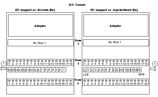
The figure below shows how data is mapped on the I/O base with an IEC Compliant adapter. When the I/O is mapped as discrete points (0x) , the MSB is assigned to Pin 1, and the LSB is assigned to Pin 16. When the I/O is mapped as a word or register (4x), the MSB (bit 15) is assigned to Pin 16, and the LSB (bit 0) is assigned to Pin 1.
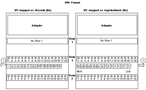
The figure below shows how data is mapped on the I/O base with a Ladder Logic Compliant adapter. When the I/O is mapped as discrete points (0x), the MSB is assigned to Pin 16 and the LSB is assigned to Pin 1. When the I/O is mapped as a word or register (4x), the MSB (bit 15) is assigned to Pin 1, and the LSB (bit 0) is assigned to Pin 16.

