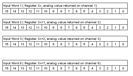
|
Analog Inputs
|
|
|
Original instructions
|
|
Word
|
Input Data
|
Output Data
|
|---|---|---|
|
1
|
Value, input channel 1
|
Parameters for input channels 1 ... 4
|
|
2
|
Value, input channel 2
|
Parameters for input channels 5 ... 8
|
|
3
|
Value, input channel 3
|
Not used
|
|
4
|
Value, input channel 4
|
Not used
|
|
5
|
Value, input channel 5
|
Not used
|
|
6
|
Value, input channel 6
|
Not used
|
|
7
|
Value, input channel 7
|
Not used
|
|
8
|
Value, input channel 8
|
Not used
|
|
Analog-to-digital conversion
|
Carried out on 14 bits + sign for bipolar input ranges,15 bits for unipolar ranges
|
|
Bit 15
|
Sign bit
|
|
Bits 14 ... 0
|
Input channel values
|

