|
Front Panel Components
|
|


|
Original instructions
|
|
Front Panel Components
|
|
|
Original instructions
|
|
Label
|
Description
|
|---|---|
|
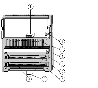
1
|
Internal interface (ATI) connector
|
|
2
|
Locking and ground contact for the adapter
|
|
3
|
LED status display
|
|
4
|
Protective cover
|
|
5
|
Sockets for the terminal connectors
|
|
6
|
Grounding screw
|
|
7
|
Busbar mounting slot
|
|
8
|
Locking tab for DIN rail mount
|
|
9
|
Mounting holes for panel mount
|
|
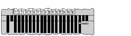
Indicator
|
Condition
|
Message
|
|---|---|---|
|
Ready
|
Green
|
Module is ready to communicate. Operating voltage for internal logic is present and self-test has been passed.
|
|
Off
|
Module is not ready. Operating voltage is not present or module is defective.
|
