This section provides diagrams to assist you in wiring the following types of devices:
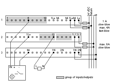
3-Wire Sensor with a 2-Wire Actuator
The diagram below shows field wiring for a 3-wire (24 VDC) sensor and a 2-wire actuator.
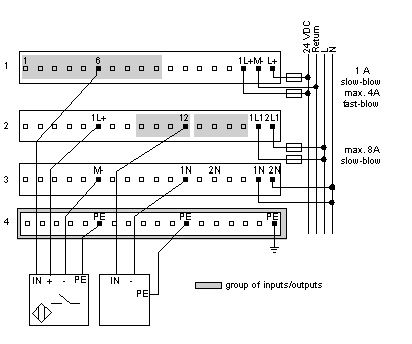
4-Wire Sensor with a 3-Wire Actuator
The diagram below shows field wiring for a 4-wire (24 VDC) sensor and a 3-wire actuator.
A 1-row busbar is used to provide PE for the 4-wire sensor. No busbar would be required if only 2- and/or 3-wire sensors were used.
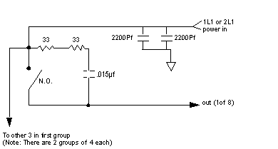
Simplified Input Schematics
The following diagram shows the field-side input circuitry.
Simplified Output Schematics
The following diagram shows the field-side output circuitry.


