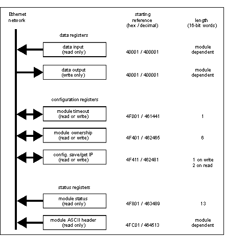
Each adapter contains three groups of registers that enable the application to communicate with the I/O base adapter.
The application accesses the registers to:
All of the parameters can be accessed as 4XXXX references by MSTR function blocks in the application program.
Communication adapter access registers
40001 hex — Data Input or Output
Starting reference 40001 is used to address input data from field inputs and output data to field outputs. Data is transferred in the IEC format. Mapping between the controller’s data registers and I/O base field terminals is unique to each base, and the mapping is described in the Momentum I/O Bases User Guide (870USE002).
To write the outputs on a Momentum I/O base, write to the 40000x registers, beginning with register 400001 (Modbus function code 16).
To read the inputs from a Momentum I/O base, read from the 40000x registers, beginning with register 400001 (Modbus function code 3).
This adapter also supports Modbus function code 23, which contains both read and write requests in a single packet.
4F001 hex — Outputs Holdup Timeout Value
Reference 4F001 specifies the amount of time that outputs will be held in their current state if they are not updated by a new Modbus TCP/IP write. If the module’s holdup time expires before a new Modbus TCP/IP write is received, all outputs are set to logical 0 (zero).
The field length is one word. The timeout value is expressed in units of 10 milliseconds. Valid values are either 0 (zero) or a range of 30 (300 milliseconds) through 6000 (60 seconds). The default value is 100 (1 second).
The registers contents can be read using a Modbus read command.
Note: The value of 0 (zero) in this register indicates an indefinite holdup time, and the outputs will not change if they are not updated by a Modbus TCP/IP write.
4F401 hex — Ownership of Write Privilege
When the adapter first receives power, it will give sole write privilege to the first node that writes to it using the Modbus write command. The adapter maintains an internal 60-second timer for handling the write privilege, and will reserve sole privilege to that node as long as the node continues to write within 60-second intervals to the adapter.
Starting reference 4F401 specifies the IP addresses of up to three more nodes which may concurrently own write privilege to the adapter. A node which currently owns the write privilege may write up to three IP addresses (2 words per address) to the adapter starting at 4F401. With those addresses stored, any of those three nodes may then write to the adapter in addition to the original privileged node. This allows up to four nodes to concurrently own write privilege to the adapter.
If writes continue to occur within the 60-second interval from any of the three privileged nodes, no other node may write to the adapter. If the timer is allowed to expire, any node may write to the adapter.
Note that this 60-second write privilege timer is separate from the outputs holdup timer, and applies only to the write privilege. The 60-second time is a fixed value and is not accessible to the application.
Any node may read the input data or status information from the adapter.
4F411 hex — Configuration Save/Get IP Address
This reference serves a dual purpose, depending on whether the application issues a Modbus TCP/IP write or a Modbus TCP/IP read. When the register issues a Modbus TCP/IP write, the register name is Configuration Save, and when the register issues a Modbus TCP/IP read, the register name is Get Current IP Address.
Modbus Write Command: Configuration Save
For a Modbus TCP/IP write, the reference is treated as a one-word register, with the application writing one word of data. The Modbus TCP/IP write data may consist of a value from 0 (zero) to 7, a bit-masked OR (the Boolean logical OR).
If a data 1 (one) is written to the reference, the adapter will save its currently assigned IP address to FLASH. If a new initialization occurs and the adapter cannot find a BOOTP server, the adapter will use this saved address.
NOTE: Any change of the Configuration Save register will cause the adapter to re-initialize. This re-initialization will occur when saving or clearing the parameters.
The configuration register values for the 4F411 hex register: Modbus TCP/IP write only.
|
Register
|
Register Decimal Value
|
Register Binary Value
|
Action
|
|
4F411 hex
|
0
|
0000
|
Clears the configuration
|
|
1
|
0001
|
Saves the configured IP to FLASH
|
|
2
|
0010
|
Saves the three (3) Master IPs addresses to FLASH
|
|
4
|
0100
|
Saves the Outputs Holdup Timeout Value to FLASH
|
Example: If you want to save outputs holdup timeout value and save the configured IP to FLASH:
-
Add the register decimal values:
1 + 4 = 5
-
Enter the decimal value 5 into the register
-
The value displays in binary:
00000101
Modbus Read Command: Get IP Address
For a Modbus read command the reference is treated as a two-word register, with the application reading two words of data. If the adapter has IP parameters saved in its non-volatile RAM, it will return its current IP address to the Modbus read command, indicating that it has stored parameters. If IP parameters are not currently saved, the adapter returns all ones (FFFFFFFF hex) to the read.
4F801 hex — Module Status Block
These registers provide information about the module’s revision level and current operating parameters.
The block’s length is 13 words. The registers can be read by the application, but cannot be written into.
NOTE: If you attempt to read a register within the diagnostic table (offset from F801), you will receive an error 3002, non-existent register requested. You must start the read at the first register of F801.
Module status block layout:
|
Reference (hex)
|
Purpose
|
Contents
|
|
4F801
|
Length of status block (words)
|
13 decimal
|
|
4F802
|
I/O module quantity of input words
|
Module dependent
|
|
4F803
|
I/O module quantity of output words
|
Module dependent
|
|
4F804
|
I/O module ID number
|
Module dependent
|
|
4F805
|
Communication adapter revision number
|
Format: XR
Where:
-
X = upper 4 bits, always 0000
-
R = lower 12 bits, defining the revision as 3 hex characters.
Example:
-
100 hex = Rev. 1.00
-
200 hex = Rev. 2.00
|
|
4F806
|
ASCII header block length (words)
|
Module dependent
|
|
4F807
|
Last IP address to communicate with this adapter in most recent Modbus transaction (low word of 2 words). See 4F80D.
|
Node address dependent
|
|
4F808
|
Remaining ownership reservation time
|
milliseconds
|
|
4F809
|
Remaining outputs holdup time
|
milliseconds
|
|
4F80A
|
I/O module health
|
8000 hex = healthy
0000 hex = not healthy
|
|
4F80B
|
I/O module last error value
|
Module dependent
|
|
4F80C
|
I/O module error counter
|
Error count 0000 ... FFFF hex
|
|
4F80D
|
Last IP address to communicate with this adapter in most recent Modbus transaction (high word of 2 words). See 4F807.
|
Node address dependent
|
4FC01 hex—Module ASCII Header Block
These registers contain an ASCII text description of the module. The registers can be read by the application, but cannot be written into.
The block length depends upon the type of I/O base to which the adapter is connected. The maximum length is 64 bytes of ASCII characters, corresponding to a length of 8 ... 32 words as specified in word 6 of the module status block (at reference 4F806).
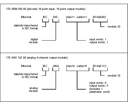
The block contains labels to identify quantities of input and output words, and the ID code of the I/O base. You can parse the block contents to extract this information in to your application.
|
ASCII Characters
|
Description
|
|
Ethernet
|
Identifies Ethernet communication adapter
|
|
20 hex (32 decimal)
|
Space
|
|
IEC
|
Data is transferred with I/O base in IEC format
|
|
20 hex (32 decimal)
|
Space
|
|
DIG:
EXP:
ANA:
|
Digital module (ID range: XX00 ... XX7F hex)
Expert module (ID range: XX80 ... XXBF hex)
Analog module (ID range: XXC0 ... XXFE hex)
|
|
20 hex (32 decimal)
|
Space
|
|
Inlen=n
|
Input words (n = quantity of words, decimal)
|
|
20 hex (32 decimal)
|
Space
|
|
Outlen=n
|
Output words (n = quantity of words, decimal)
|
|
20 hex (32 decimal)
|
Space
|
|
ID=0xnnnn
|
Module DI code (nnnn = ID code, hex)
|
Examples of the ASCII header block contents for two I/O bases:

 WARNING
  CAUTION