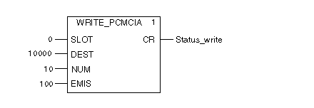
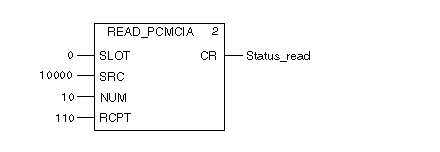
This example shows how to use the READ_PCMCIA and WRITE_PCMCIA function blocks by:
NOTE: In this example, to use those function blocks, a memory card must be connected into the PLC.
In this example, the TSX MRP C007M SRAM memory card is connected into the upper slot A of the CPU (parameter SLOT = 0 for the functions blocks). In addition, for data storage purposes, the CPU is configured with 2000 kB of memory.
NOTE: The data storage is used for READ_PCMCIA and WRITE_PCMCIA function blocks. The 2000 kB of data storage represents:
The READ_PCMCIA and WRITE_PCMCIA functions are working with word addresses:
Addresses from 0 to 1024000 for the memory card can be used.
Programming the MAST section
In the MAST section of the program, program as follows:
-
The memory card is connected into slot 0.
-
The WRITE_PCMCIA function writes 10 words to address 10000 on the memory card from %MW100.
-
The READ_PCMCIA reads 10 words from address 10000 on the memory card to %MW110.
Representation of WRITE_PCMCIA and READ_PCMCIA in FBD language:
Representation of WRITE_PCMCIA and READ_PCMCIA in ST language:
WRITE_PCMCIA (0,10000,10,100,Status_write);
READ_PCMCIA (0,10000,10,110,Status_read);
By using animation tables with words: %MW100 to %MW119, the values from %MW100 to %MW109 are copied to %MW110 to %MW119 via the memory card.


