|
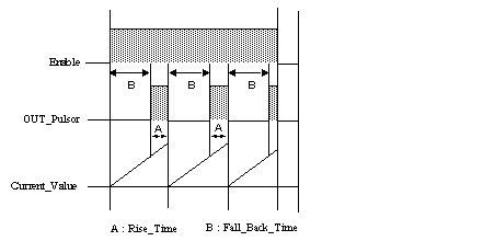
Detailed description of the operation of the FPULSOR function
|
|
|
Original instructions
|

|
Phase
|
Action
|
Description
|
|---|---|---|
|
1
|
Rising edge on the Enable input
|
The generation of the rectangular signal is launched: (if the signal is not already increasing) its current value increases by 0 towards Rise_Time+Fall_Back_Time (in hundredths of seconds).
|
|
2
|
As long as the Fall_Back_Time time out has not run out
|
The output bit OUT_Pulsor remains at 0.
|
|
3
|
Fall_Back_Time has elapsed, Rise_Time is activated
|
The output bit OUT_Pulsor changes to 1 until the end of Rise_Time and the generator loops on steps 2 and 3.
|
|
4
|
Enable switches to 0
|
Rise_Time and Fall_Back_Time are reset to 0, and the output OUT_Pulsor switches to 0.
|