|
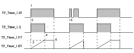
Detailed description of the operation of the PL7_TP function
|
|
|
Original instructions
|

|
Phase
|
Description
|
|---|---|
|
1
|
When there is a rising edge on the TP_Timer_1.S, input the timer is started
|
|
2
|
The output bit TP_Timer_1.Q changes to 1.
|
|
3
|
The current value TP_Timer_1.ET of the timer increases from 0 towards TP_Timer_1.PT at a rate of one unit for each pulse of the time base TB
|
|
4
|
The output bit TP_Timer_1.Q falls to 0 again as soon as the current value reaches TP_Timer_1.PT
|
|
5
|
When the TP_Timer_1.IN input and the TP_Timer_1.Q output are at 0, TP_Timer_1.ET takes the value 0.
|
|
6
|
This monostable cannot be reset.
|