Introduction
The following diagrams present examples of M580 safety topologies. This collection of sample topologies does not include every potential topology supported by an M580 safety system.
Refer to the Modicon M580 Standalone System Planning Guide for Frequently Used Architectures, the Modicon M580 System Planning Guide for Complex Topologies, and the Modicon M580 Hot Standby, System Planning Guide for Frequently Used Architectures for additional information on how to set up an M580 topology.
Extending the Local Main Rack
The following diagram presents a local main rack, with two extended racks. Note that the M580 safety system supports a single local main rack plus up to seven extended racks over a maximum length of 30 m:
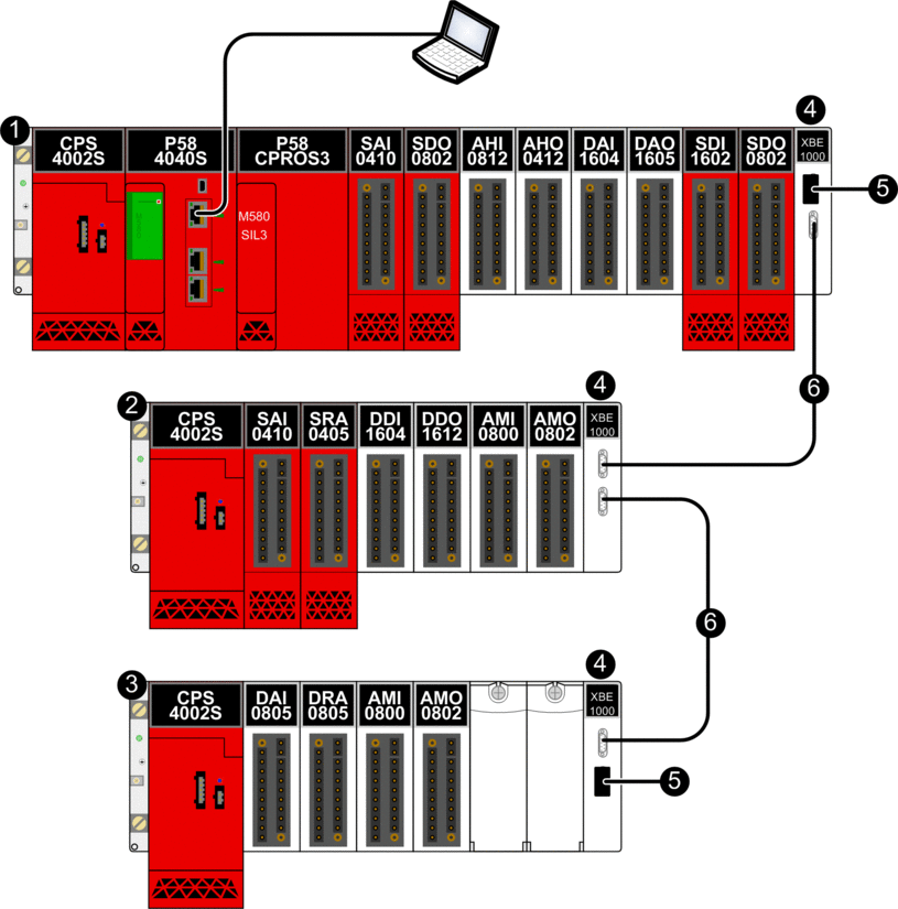
1 Local main rack with safety and type 1 non-interfering modules
2 Local extended rack with safety and type 1 non-interfering modules
3 Local extended rack with type 1 non-interfering modules
4 BMXXBE1000 rack extender modules
5 TSXELYEX line terminators
6 BMXXBC•••K connector cables
High Availability I/O Topologies
The following diagram presents an example of redundant I/O placed in the same RIO drop:
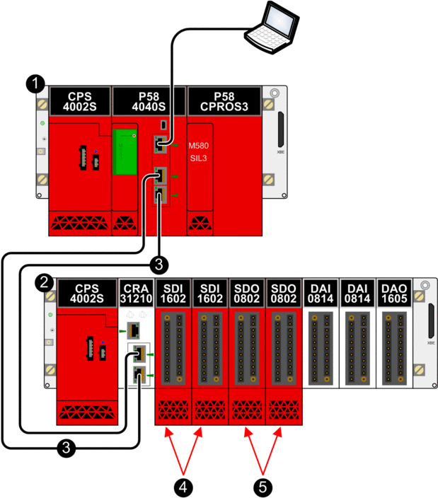
1 Local main rack
2 RIO drop
3 RIO main ring
4 Two redundant input modules in the same RIO drop
5 Two redundant output modules in the same RIO drop
The following diagram presents an example of placing redundant I/O in two separate RIO drops:
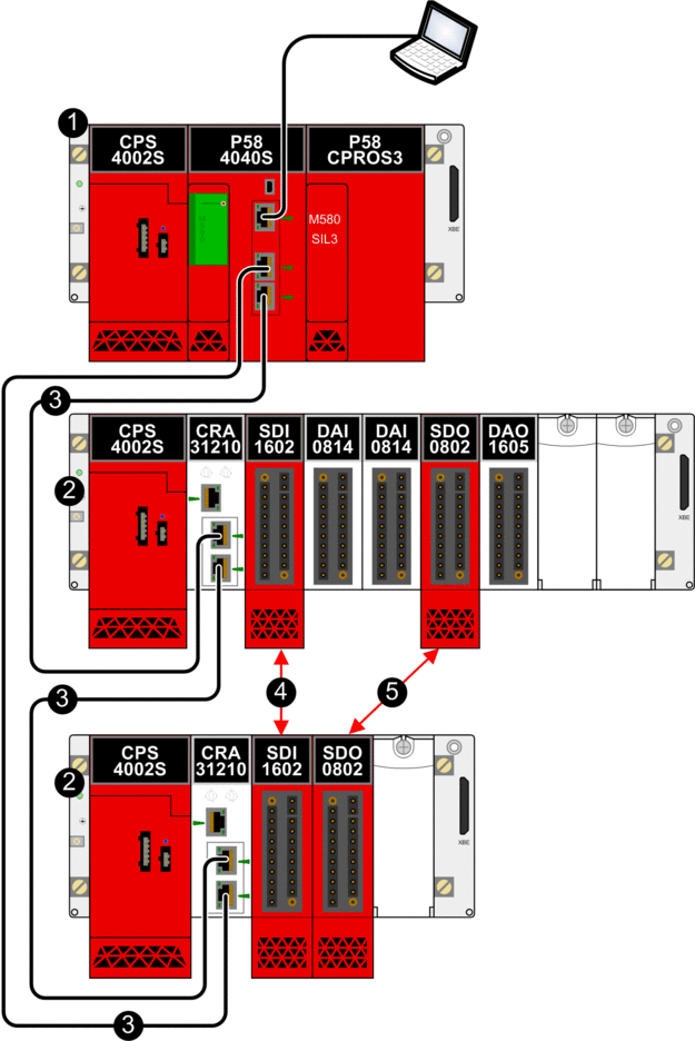
1 Local main rack
2 RIO drop
3 RIO main ring
4 Two redundant input modules in separate RIO drops
5 Two redundant output modules in separate RIO drops
Schneider Electric recommends placing redundant safety I/O modules in separate RIO drops.
With CPU firmware 3.10 or earlier, enable the NTP service for the M580 safety PAC to support black channel communication between the local main rack and RIO drops on the RIO main ring. The safety PAC can be either the NTP server, or the NTP client (with another device configured as the NTP server).
Peer-to-Peer Topology for Two Standalone Safety PACs
The following diagram presents an example of how to connect two separate M580 safety PACs. In this example, a sensor linked to a safety input module in PAC 1 can be configured to cause a response by an actuator linked to a safety output module in PAC 2:
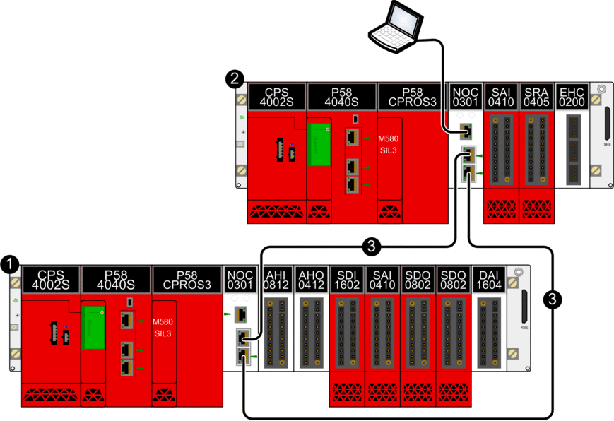
1 Standalone M580 safety PAC 1
2 M580 safety PAC 2
3 Black channel communication between PACs
Adding Distributed Equipment to the M580 Safety PAC
You can add type 1 and type 2 non-interfering modules to your M580 safety project as distributed equipment, in either a non-looping daisy chain or a daisy chain loop design.
The following diagram depicts an example of distributed equipment added as a non-looping daisy chain. In this example, the distributed equipment daisy chain connects to the PAC via the ETH2 and ETH3 EIO ports of a BMENOC0301/11 Ethernet communications module:
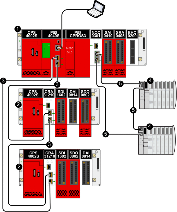
1 Local main rack with Ethernet backplane
2 RIO drop with safety modules and type 1 non-interfering modules
3 RIO main ring
4 Distributed equipment
5 Ring of distributed equipment
Hot Standby Topology
The following diagram presents a Hot Standby topology:
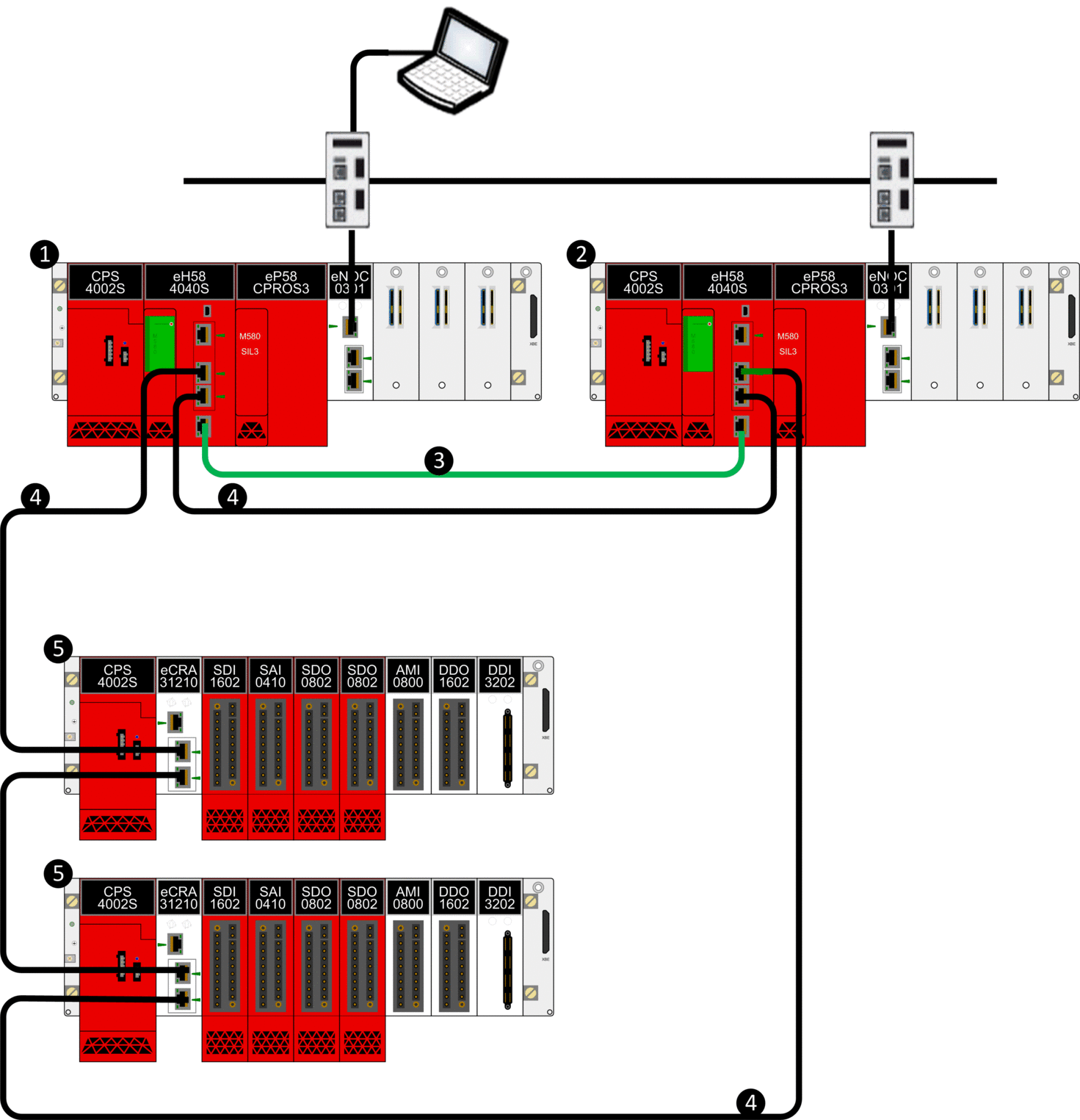
1 Primary local rack with primary CPU
2 Standby local rack with standby CPU
3 Hot Standby communication link
4 Ethernet RIO main ring
5 (e)X80 RIO drop


