Positioning Safety I/O Modules
You can install an M580 safety I/O module on:
the local rack in any slot that is not reserved for the power supply or CPU.
a remote rack in any slot that is not reserved for the power supply or remote adapter.
Safety I/O Module Front Panel
The front panel of each safety I/O module presents the following features:
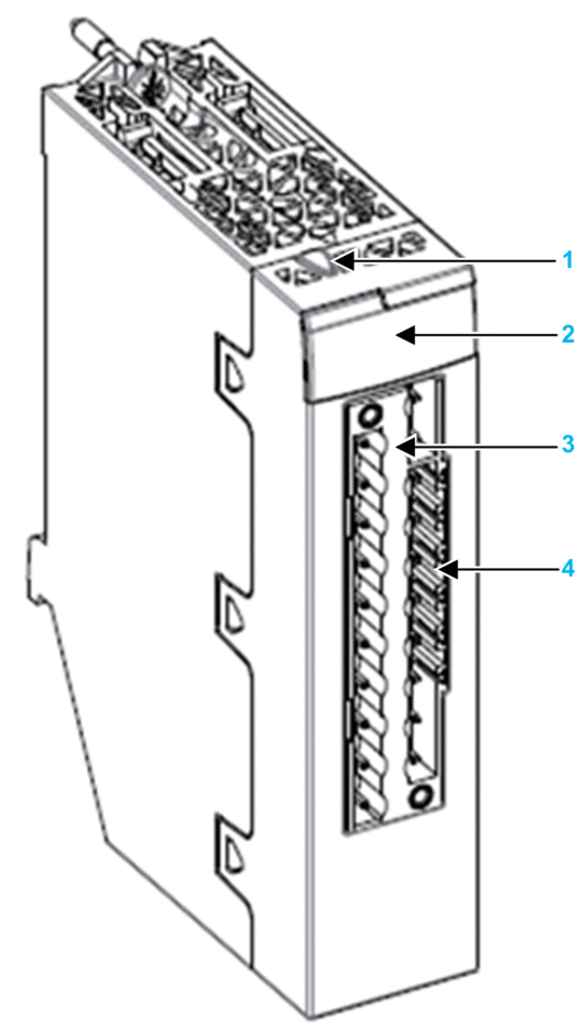
1 Lock / Unlock configuration button
2 LED panel
3 20-pin connector
4 Keying pin slots
Safety I/O Module Dimensions
Each safety I/O module presents the following physical dimensions:
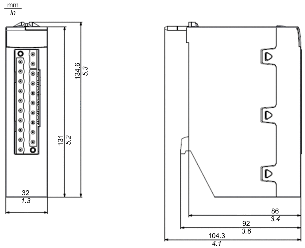
29.49 mm (1.161 in.) for an Ethernet rack
30.9 mm (1.217 in.) for an X Bus rack
Safety I/O Wiring Dimensions
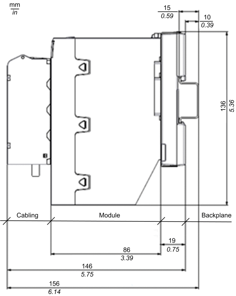
Each safety I/O module presents the following wiring dimensions:
LEDs
Each safety I/O module provides module and channel LED diagnostics on the front face of the module:
The top four LEDs (Run, Err, I/O, and Lck) together describe the state of the module.
The bottom rows of LEDs combine with the top four LEDs to describe the state and health of each input or output channel.
BMXSAI0410 safety analog input module, and BMXSRA0405 safety digital relay output module LEDs:
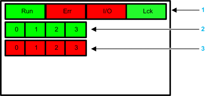
1 Module state LEDs
2 Channel state LEDs
3 Channel detected error LEDs
BMXSDI1602 safety digital input module LEDs:
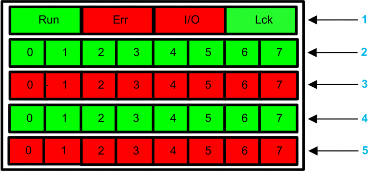
1 Module state LEDs
2 Channel state LEDs for Rank A
3 Channel detected error LEDs for Rank A
2 Channel state LEDs for Rank B
3 Channel detected error LEDs for Rank B
BMXSDO0802 safety digital output module LEDs:
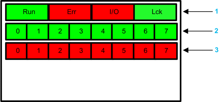
1 Module state LEDs
2 Channel state LEDs
3 Channel detected error LEDs


