Introduction
This topic discusses distributed equipment that is connected only to a BMENOS0300 on a local rack (not an RIO drop).
High Capacity Subsystem Example
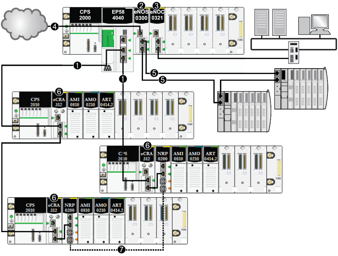
This illustration shows a simple daisy chain loop with a BMENOS0300 module that communicates with distributed equipment:

1 A CPU with Ethernet I/O scanner service is on the local rack and connected to the main ring.
2 A BMENOS0300 network option switch module on the local rack manages distributed equipment.
3 A BMENOC0321 control network module on the local rack creates transparency between the device network and the control network.
4 A BMENOS0300 network option switch module on the local rack manages a DIO cloud.
5 The BMENOS0300 network option switch module on the local rack manages a DIO sub-ring.
6 A BMECRA312•0 eX80 adapter module is installed on each remote drop.
7 BMXNRP020• fiber converter modlues on remote drops are connected to extend the distance between drops. (Refer to the documentation for the BMXNRP020• fiber converter module.)
In this complex M580 network topology (which consists of a main ring and multiple sub-rings), these restrictions apply:
The maximum number of... |
...is... |
|---|---|
hops in a network path |
17 |
RIO modules in the main ring |
16 |
distributed equipment on the network |
128 per scanner; there may be several BME NOCs in the system with the CPU |


