Introduction
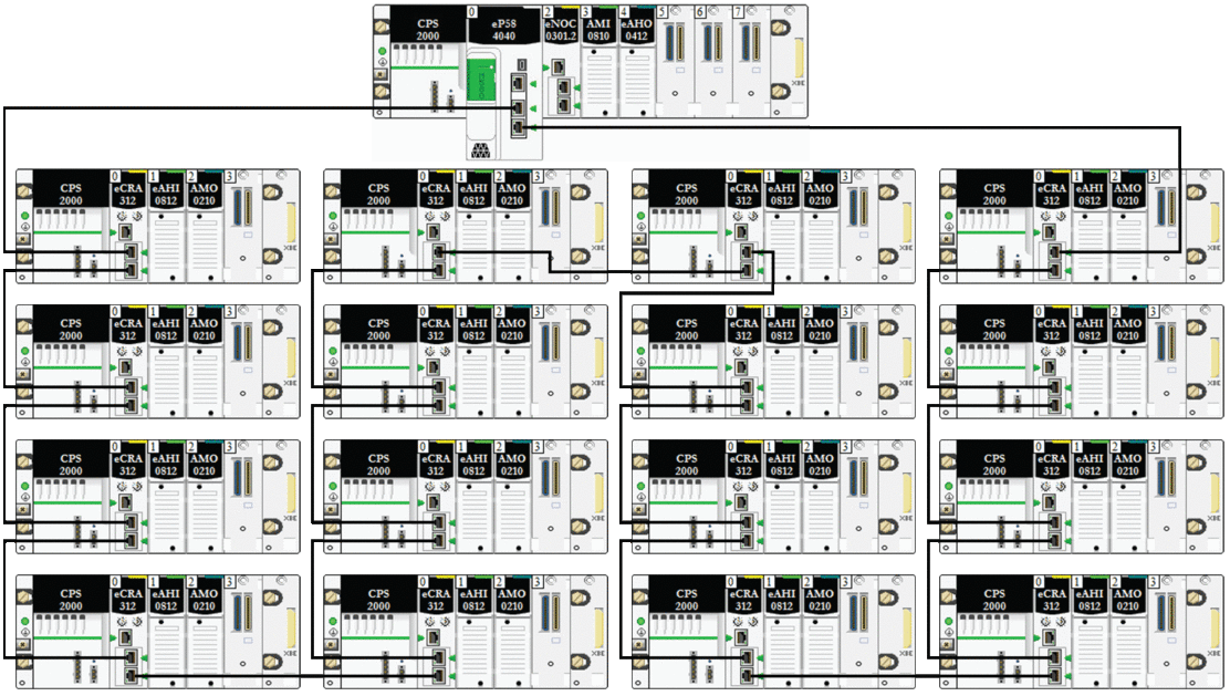
A simple daisy chain loop contains a local rack and one or more RIO drops on a main RIO ring.
Implement a simple daisy chain loop network if only Ethernet RIO drops are included in the loop. The maximum number of RIO drops in the loop is 31. The local rack consists of a CPU with Ethernet I/O scanner service.
Requirements
A simple daisy chain loop configuration provides cable redundancy that anticipates possible communication disruptions such as a broken wire or a non-operating RIO drop. Detecting a break in the main ring is discussed later in this guide.
This graphic shows a CPU with Ethernet I/O scanner service in the local rack and Ethernet RIO drops on the main ring that include BM•CRA312•0 X80 EIO adapter modules:

Verify that the CPU in the local rack supports RIO scanning. You can also add a maximum of six communication modules, depending on the CPU selection.
A maximum of 31 remote drops is supported.
Only copper cable can be used, so there is a maximum distance of 100 m between any two consecutive RIO modules on the main ring. If you want to extend the distance beyond 100 m, use BMXNRP020• fiber converter modules to convert the copper cable to fiber.
If you connect a DIO cloud to the CPU on the local rack, the cloud is not part of the simple daisy-chain loop. The CPU services the control logic for the DIO cloud only after it has completed the logic scan for the RIO.
Planning a Simple Daisy Chain Loop
Follow the steps below to plan a simple daisy chain loop network. Configuration procedures are discussed in the respective Modicon M580 Ethernet communication/adapter module user guide.
Step |
Action |
|---|---|
1 |
Plan the local rack (including the M580 CPU with Ethernet I/O scanner service and the power supply module. |
2 |
Plan the Ethernet RIO drops. (Each drop includes a BM•CRA312•0 X80 EIO adapter module.) |
3 |
Select a CPU that supports RIO and configure the Ethernet I/O scanner service for RIO. |
4 |
Connect the Device Network port on the CPU to an Ethernet port on the adapter module at one of the drops. This completes the loop. Do not use the Service port or ETH 1 port on the CPU and on the BM•CRA312•0 X80 EIO adapter modules for this connection unless in some specific conditions described in Modicon M580, Open Ethernet Network, System Planning Guide. The Service port may not provide full performance and features that the Device Network ports on provide. Connecting the Service port, either directly or through a switch/hub, to the Device network may affect system performance. |
CPUs and eX80 EIO adapter modules do not have fiber ports. Therefore, the maximum distance between the CPU and the first drop and between any two contiguous drops is less than 100 m, using shielded twisted 4-pair CAT5e or greater (10/100 Mbps) cable. (Do not use twisted 2-pair CAT5e or CAT6 cables.) If you want to extend the distance beyond 100 m, use DRSs or BMX NRP 020• fiber converter modules to convert the copper cable to fiber.
The Ethernet ports are clearly labeled on both the CPU with Ethernet I/O scanner service and the BM•CRA312•0 X80 EIO adapter module. If you connect these modules to the wrong ports, system performance will be affected.
Connecting the BMENOC0321 Module to a Device Network
Provide network transparency between the control network and a device network:
Step |
Action |
|---|---|
1 |
Install one CPU, up to three BMENOC0301/BMENOC0311 Ethernet communication modules that communicate with the CPU and one BMENOC0321 control module on the local rack. |
2 |
Confirm that the Ethernet backplane ports are enabled for the BMENOC0301/BMENOC0311 modules (up to five), the BMENOC0321 module, and the CPU. |
3 |
Connect the start of the main ring to the device network port (ETH 2 or ETH 3) of the CPU. |
4 |
Connect the end of the main ring to the device network port (ETH 2 or ETH 3) of the CPU. |
5 |
Connect the control network port (ETH 2 or ETH 3) of the BMENOC0321 module to the control network. |
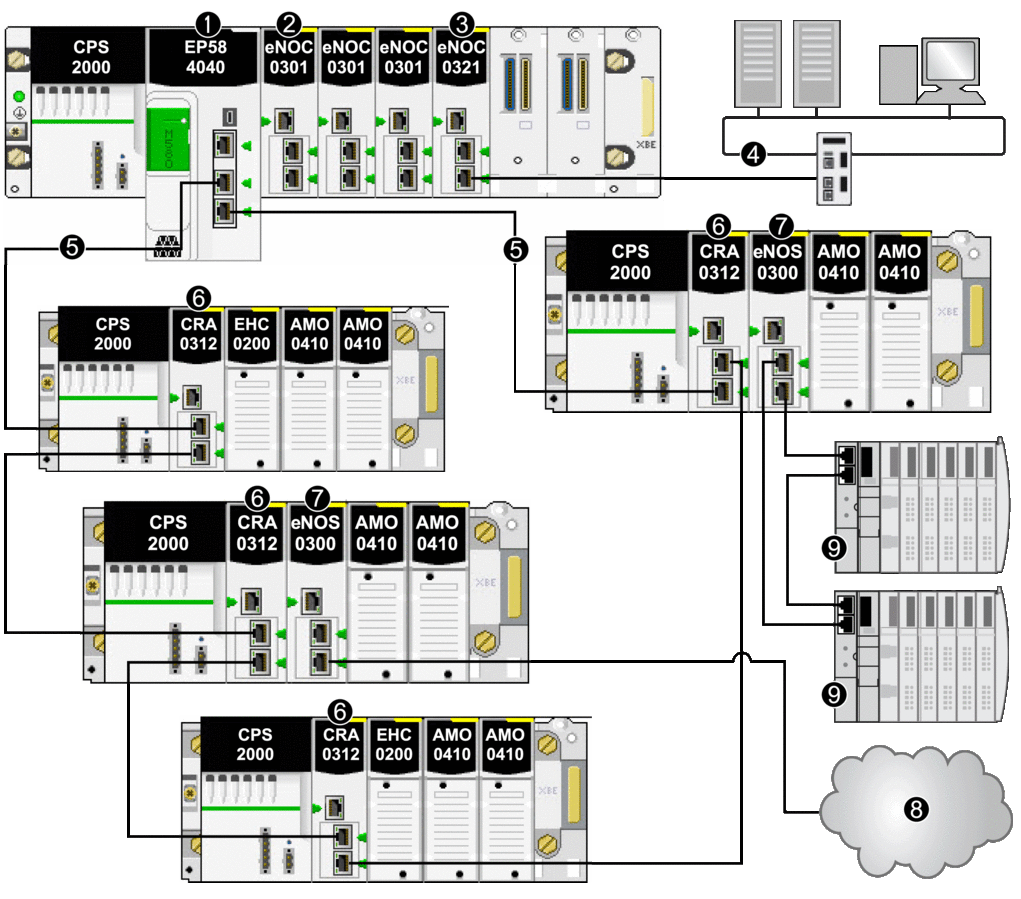
Sample architecture:

1 BME•58•••• CPU connecting the local rack to the main ring
2 BMENOC0301/BMENOC0311 Ethernet communication module managing distributed equipment on the device network
3 BMENOC0321 control network module, providing transparency between the device network and the device network
4 control network
5 RIO main ring
6 BM•CRA312•0 (e)X80 EIO adapter module on an RIO drop on the main ring
7 BMENOS0300 module on an RIO drop
8 DIO cloud connected to the main ring via a BMENOS0300 network option switch module on an RIO drop
9 STB island in a DIO sub-ring connected to the main ring via a BMENOS0300 module on an RIO drop


