Representation
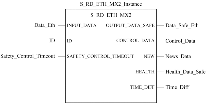
DFB representation:

Refer to the EcoStruxure™ Control Expert, Safety, Block Library for an extended description of this DFB.
Description
The S_RD_ETH_MX2 DFB is for PAC using CPU firmware 3.20 or later.
It copies the data received in the process area to the safety area
and validate the accuracy of the received data.
| WARNING | |
|---|---|
The S_RD_ETH_MX2 function block:
Copies the data received in the
INPUT_DATAregister to theOUTPUT_DATA_SAFEregister if it passes the following tests:The function block checks the CRC of the last data packet received, via I/O scanner over Ethernet (Modbus TCP). If the CRC is not correct, the data is considered as unsafe and it is not written to the
OUTPUT_DATA_SAFEregister in the safety area.The function block checks the last data received to determine if it is more recent than the data already written in the
OUTPUT_DATA_SAFEregister in the safety area (by comparing time stamps). If the last data received is not more recent, it is not copied to theOUTPUT_DATA_SAFEregister in the safety area.
Checks the age of the data in the safety area. If the age is higher than a configurable maximum value set in the
SAFETY_CONTROL_TIMEOUTinput register, the data is declared unsafe and theHEALTHbit is set to 0.NOTE: The data age is the time difference between the time when the data is computed in the sender PAC and the time when the data is checked in the receiver PAC.If the
HEALTHbit is set to 0, the data available in theOUTPUT_DATA_SAFEarray is considered as unsafe. In this case, take the appropriate reactive steps.
INPUT_DATA and OUTPUT_DATA_SAFE Arrays Description
The INPUT_DATA arrays consist of data coming from the process
data memory area. The OUTPUT_DATA_SAFE arrays consist
of safety variables. Use the and the tabs in Control Expert to make
the link between the process variables and the safety variables.
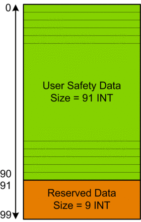
INPUT_DATA and OUTPUT_DATA_SAFE arrays are composed of 2 zones:
The User Safety Data zone contains user data. This zone starts at index 0 and finishes at index 90.
The Reserved Data zone is reserved for auto-generated diagnostic data, including a CRC and time-stamp. This data is used by the receiving PAC to determine if the data contained in the User Safety Data zone is safe or not. This zone starts at index 91 and finishes at index 99.
NOTE: Writing in the Reserved Data zone is not recommended, as doing so will overwrite the auto-generated diagnostic data.
INPUT_DATA and OUTPUT_DATA_SAFE arrays (array[0..99] of INT) structure representation:

CONTROL_DATA Array Description
The CONTROL_DATA array has to be linked with variables in “Global”
area (defined through the “Safety Data Interface”) and
then, “Global” variables have to be linked to located
variables in “Process” area (defined through the “Process
Data Interface”) in order the data to be sent by IO Scanner
to the correspondent sender.
Calculating a SAFETY_CONTROL_TIMEOUT Value
When calculating a SAFETY_CONTROL_TIMEOUT value, consider the following:
Minimum value:
SAFETY_CONTROL_TIMEOUT>2 * T1Recommended value:
SAFETY_CONTROL_TIMEOUT> 3 * T1
T1 = CPUsender MAST cycle time + CPUsender SAFE cycle time + Repetitive_rate + Network transmission time + CPUreceiver MAST cycle time + CPUreceiver SAFE cycle time
Where:
CPUsender MAST cycle time is the MAST cycle time of the sender PAC.
CPUsender SAFE cycle time is the SAFE cycle time of the sender PAC.
Repetitive_rate is the time rate for the I/O scanner write query from the sender PAC to the receiver PAC.
Network transmission time is the time consumed on the Ethernet network for the data transmission from the sender PAC to the receiver PAC.
CPUreceiver MAST cycle time is the MAST cycle time of the receiver PAC.
CPUreceiver SAFE cycle time is the SAFE cycle time of the receiver PAC.
Note that the value defined for the SAFETY_CONTROL_TIMEOUT parameter has a direct effect on the robustness and availability
of the safe peer-to-peer communication. If the SAFETY_CONTROL_TIMEOUT parameter value greatly exceeds T1, the communication will be tolerant
to various delays (for example network delays) or corrupted data transmissions.
You are responsible for configuring your Ethernet network so the load that does not cause an excessive delay on the network during data transmission, which could lead to the expiration of the timeout. To help safeguard your safe peer-to-peer communications from any excessive delays due to other non-safety data transmitted on the same network, consider using a dedicated Ethernet network for the safe peer-to-peer protocol.
When commissioning your project, you have to estimate
the safe peer-to-peer communication performance by checking the values
provided in the output parameter TIME_DIFF and evaluating
the margin using the value defined in the SAFETY_CONTROL_TIMEOUT parameter.
Understanding the HEALTH Bit
When the HEALTH bit value equals:
1: The integrity of the data is correct (CRC) and the age of the data is less than the value set in the
SAFTETY_CONTROL_TIMEOUTinput register.NOTE: The age of the data considered is the time between:The beginning of the cycle where the data are computed in the sender PAC.
The beginning of the cycle where the data are checked in the receiver PAC.
0: New valid data are not received in the required time interval (the timer expires and the
HEALTHbit is set to 0).NOTE: If theHEALTHbit is set to 0, the data in the output arrayOUTPUT_DATA_SAFEis considered to be unsafe; respond accordingly.


