Architecture Design
Using CPU firmware 3.20 or later, the solution architecture is based on:
Execution of 2 DFBs (
S_WR_ETH_MX2andMOVE) in the sender PAC and 2 DFBs (S_RD_ETH_MX2andMOVE) in the receiver PAC.Scanning via Modbus TCP, for safe data transportation from Sender to Receiver.
Scanning via Modbus TCP, for control data transportation from Receiver to Sender.
The following figure shows the overview of the process required to perform the safe peer-to-peer communication:
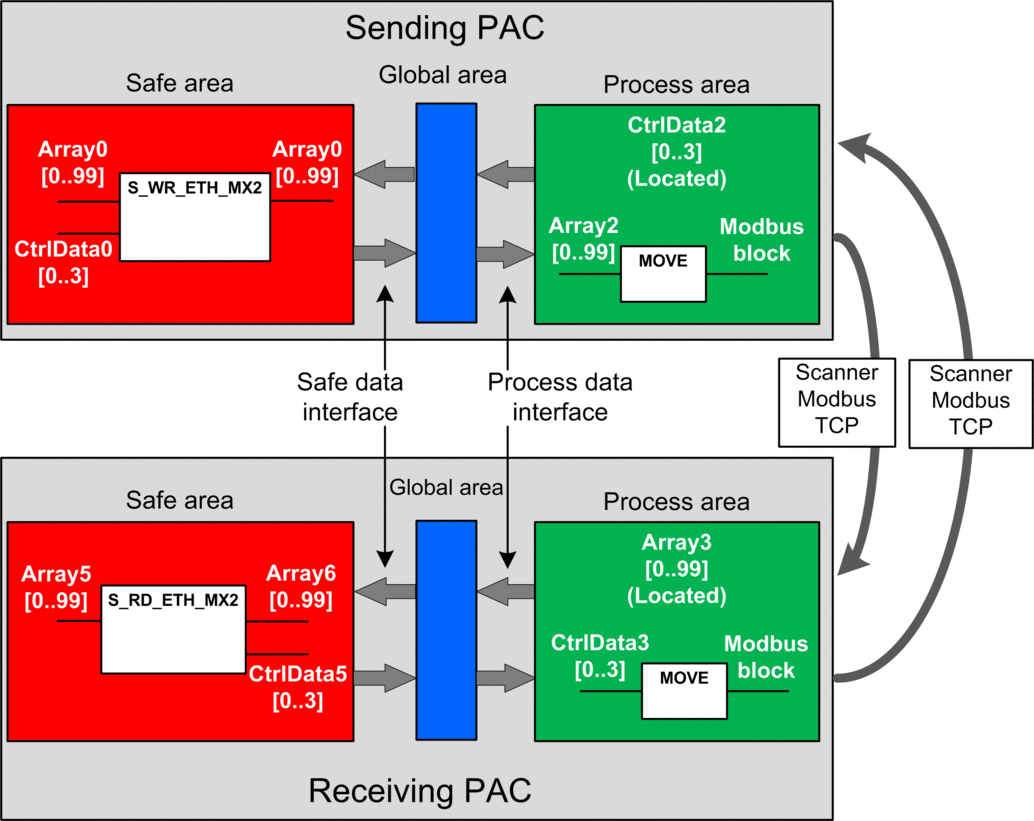
In the figure above, Control Expert automatically creates – and hides from external view – Array1 and Array4 in the Global areas of the peer PACs. From a user standpoint, the links are made from Array0 to Array2, and from Array3 to Array5.
Peer-to-Peer Data Transfer Configuration Details
The following example shows you how to configure a peer-to-peer transfer of data between two safety PACs with firmware 3.20 or later and Control Expert 15.0 or later:
Step |
Action |
|---|---|
1 |
On the sending PAC, use the to create a 100-integer array (Array2) as an input in the Interface area. Create in the same a 4-Integer array (CtrlData2) as an output in the area. The control data from the receiving PAC will be written into this CtrlData2 via the Modbus scanner, provided this CtrlData2 is located at the address defined in scanner of the sending PAC (in this example %MW100 – see Step 14):  |
2 |
On the sending PAC, use the to create another 100-integer array (Array0) as an output in the area and link it to the process.Array2 data created in step1, above, in the column. Create in the same an array of 4-Integer array (CtrlData0) as an input in the safety area and link it to the process.CtrlData2 data created in step1, above, in the column.  NOTE: The integer variables from index 0 to 90 of
the array contain the safety variable values you want to exchange
with the receiving PAC. The remaining area is reserved for auto-generated
diagnostic data, including a CRC and time-stamp. This diagnostic data
is used by the receiving PAC to determine if the transferred data
is safe.
|
3 |
On the sending PAC, configure the DFB  |
4 |
In the of the sending PAC, select the CPU (in this example) or an NOC communications module (if any) then click to create a Modbus scanner that can send data via Modbus TCP from the sending PAC to the receiving PAC: 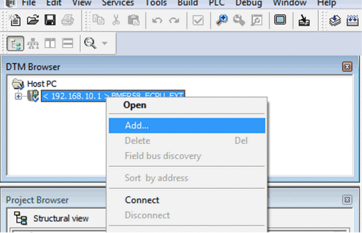 |
5 |
Select and click to add the Modbus scanner: 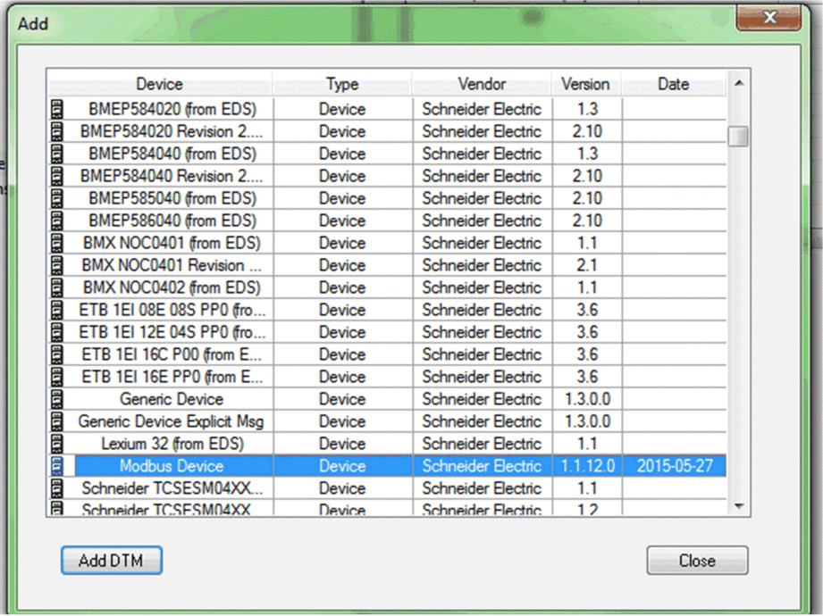 |
6 |
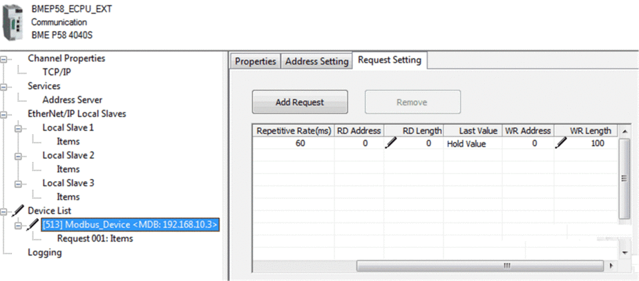
Open the newly added Modbus device, and in the tab:
|
7 |
Select the node, then in the tab define an array type of INT (that is ≥100 integers). This is the sending PAC table that will be written to the receiving PAC: 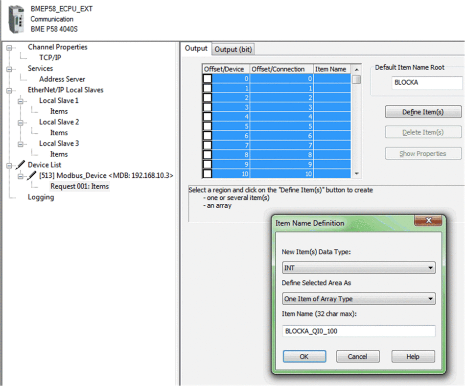 |
8 |
After saving and building the configuration, the block (BLOCKA_QI0_100 in his example) is automatically created as a process variable:  |
9 |
On the sending PAC, in a process code section, use a  |
10 |
On the receiving PAC, use the to create a 100-integer array (Array5) as an input in the area. Create in the same a 4-integer array (CtrlData5) as an output in the area. 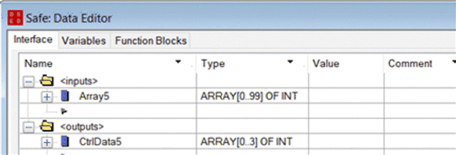 |
11 |
On the receiving PAC, in the , create a 100-Integer array (Array3) as an output of the area. Link this Array3 to the Array5 (created in step 10) in the column. The data from the sending PAC will be written into this Array3 via the Modbus scanner, provided this Array3 is located at the address defined in scanner of the sending PAC (in this example %MW0). Create in the same a 4-integer array (CtrlData3) as an input in the area. Link this CtrlData3 to the CtrlData5 (created in step 10) in the column.  |
12 |
On the receiving PAC, use the to create a 100-integer array (Array6): 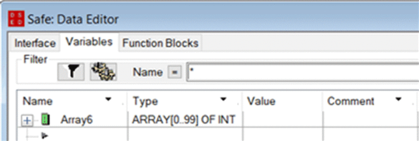 |
13 |
On the receiving PAC, in a section of code in the SAFE task,
instantiate the 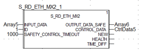 |
14 |
On the receiving PAC, redo Step 4 to 9 to configure a 4-Integer communication to send the CtrlData2 array from receiving PAC to sending PAC. In this example the CtrlData must be written to the sending PAC at address %MW100. |
Black Channel Peer-to-Peer
Each peer-to-peer data transmission consists of both User Safety Data, which contains the application-related content being transmitted, and Reserved Data. The Reserved Data is used by the safety PAC to test the reliability of the transmission so that it satisfies the requirements of SIL3. The Reserved Data consists of the following elements:
A CRC calculated by the sending PAC from the data to be transmitted. The receiving PAC checks the CRC before using the transmitted data.
A communication identifier, which is included in the CRC calculation to help prevent masquerade and insertion attacks on the transmission of safety data.
A time stamp, containing the time of the transmission in ms. With CPU firmware 3.20 or later this stamped time is the safe time value provided by the receiver CPU. The data sender PAC adds a time value to the data sent to the receiver PAC. The receiver PAC compares the received time stamp with its own time value, and uses it to:
Check the age of the data.
Reject duplicate transmissions.
Determine the chronological order of received transmissions.
Determine the elapsed time between receipt of data transmissions.


