

Introducing the Schneider Electric M580 Safety Function
Using Control Expert with Safety, you can program, configure and maintain a safety application. When designing and programming your safety application, apply safety functions only to components of a safety loop.
After commissioning, while your M580 safety system is operating in safety mode, the safety system periodically reads safety inputs, processes the application program safety logic, performs diagnostics, and applies the logic results to safety outputs.
If CPU or I/O diagnostics detect an error, the safety system places the affected part of the system into a safe state. Depending on the nature of the detected error, the scope of the response may place a single I/O channel, an I/O module, or the entire system into the safe state.
The safe state is always the de-energized state. For example:
If the BMXSAI0410 analog input module or the BMXSDI1602 digital input module detects a dangerous internal condition, it sets the value of their inputs to the CPU to “0” (the de-energized state), which remain in that state until the underlying condition has been resolved.
If the BMXSDO0802 digital output module or BMXSRA0405 digital relay output module detect a dangerous internal condition, it sets its outputs to the de-energized state, which remain in that state until the underlying condition has been resolved and the module is restarted.
If the BMXSDO0802 digital output module or BMXSRA0405 digital relay output module detects a communication error on a black channel link to the CPU, the output module sets its outputs to their fallback state.
NOTE: You can use Control Expert Safety to configure the fallback state (energized, de-energized, or maintain last value) in the event black channel communication between the CPU and output module is lost.If a BMEP58•040S standalone or a BMEH58•040S Hot Standby CPU detects a communication error on a black channel link to a safety input module, it sets the state of the affected inputs to “0” (the de-energized state) until the black channel again becomes operational and the CPU can again read actual input values.
Safety Loop
A safety loop is the collection of equipment and logic that executes a safety process. A safety project can include multiple safety loops. For each safety loop, you need verify that:
The process safety time is greater than the system reaction time.
The sum of the PFD or PFH values for all components in the safety loop does not exceed the maximum permitted value for the intended:
safety integrity level (1, 2, 3, or 4)
mode of operation (low demand or high demand)
proof test interval
Include only safety equipment in a safety loop. Although you can include non-interfering modules in your safety project, use them only for non-safe (MAST, FAST, AUX0, or AUX1) tasks.
| WARNING | |
|---|---|
Refer to the topic Data Separation in an M580 Safety Project for a description of global area variables.
Safety Loop:
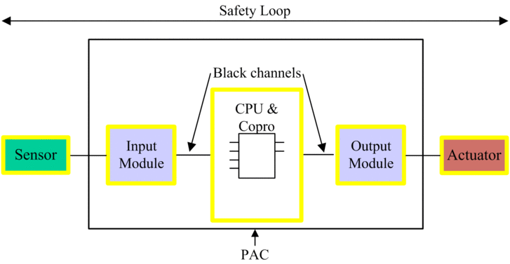
Safety equipment includes the following Schneider Electric M580 safety modules:
BME•58•040S CPU & BMEP58CPROS3 Copro:
The CPU & Copro together perform the tasks of reading safety inputs, processing safety logic, performing diagnostics, and applying results to outputs. All of these tasks are part of the safety loop. Ports used for black channel communications are also part of the safety loop. However, other CPU components – for example the USB port, SD memory card, and non-volatile static random access memory (nvSRAM) area – are not part of the safety loop.
NOTE: On both a cold and a warm system start, the CPU & Copro do not load data stored in nvSRAM into the safety task. (nvSRAM data is used only in the non-safe MAST, FAST, and AUX tasks). Instead, the CPU & Copro initially apply default configuration settings from the SD memory card, then apply values received directly from inputs during operation.Safety I/O (BMXSAI0410, BMXSDI1602, BMXSDO0802, and BMXSRA0405):
The functions of sending input signals, receiving output signals, and performing diagnostics are part of the safety loop.
BMXCPS4002S, BMXCPS4022S, and BMXCPS3522S power supplies:
These safety power supplies provide over-voltage detection, and this is part of the safety loop. Because each power supply reliability (i.e. its dangerous failure rate) is more than 100 times better than the threshold for the SIL3 standard, these safety power supplies are not included in safety integrity level calculations for the safety loop.
The safety loop also includes the following non-safety equipment:
Sensors, actuators and the cabling that connects them to safety I/O modules.The safety I/O perform wiring diagnostics for sensors and actuators to help manage the safety loop.
NOTE: When you design your safety application, you need to identify sensor and actuator characteristics (in particular PFD/PFH values).