LED Panel
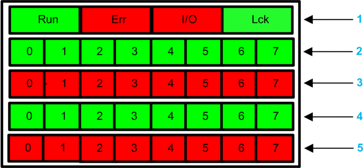
The BMXSDI1602 digital input module presents the following LED panel on its front face:

1 Module state LEDs
2 Channel state LEDs for Rank A
3 Channel detected error LEDs for Rank A
4 Channel state LEDs for Rank B
5 Channel detected error LEDs for Rank B
Module Diagnostics
Use the four LEDs at the top of the LED panel to diagnose the condition of the BMXSDI1602 digital input module:
Module LEDs |
Module State |
Recommended Response |
|||
|---|---|---|---|---|---|
Run |
Err |
I/O |
LCK |
||
Blinking |
Blinking1 |
Blinking1 |
Blinking1 |
Auto-test at power-on. |
– |
Blinking |
ON |
OFF |
Blinking1 |
Auto-test at power-on has detected an internal error on input channels. |
Replace the module. |
Blinking |
ON |
ON |
Blinking1 |
|
Verify the external pre-actuator 24 Vdc power supply is operational, and connect the 24 Vdc supply. |
OFF |
ON |
OFF |
OFF |
Internal error detected. |
Replace the module if the condition persists. |
OFF |
Blinking1 |
OFF |
X |
Non-configured I/O module. |
Configure the module via the CPU. |
X |
XX |
ON |
X |
|
|
ON |
Blinking1 |
X |
X |
No communication between CPU and module. |
Verify that:
|
ON |
Flickering2 |
X |
OFF |
Communication not safe and configuration unlocked. |
Debug the condition using the DDDT variables for the I/O module instance. |
ON |
Flickering2 |
X |
ON |
Communication not safe and configuration locked. |
|
ON |
ON |
OFF |
X |
Input channel Internal error detected. |
Replace the module if the condition persists. |
ON |
OFF |
OFF |
OFF |
Communication with CPU is OK and the configuration is unlocked. |
– |
ON |
OFF |
OFF |
ON |
Communication with CPU is OK and the configuration is locked. |
– |
X indicates the LED state can be either ON or OFF. 1. Blinking: 500 ms ON / 500 ms OFF. 2. Flickering: 50 ms ON / 50 ms OFF. |
|||||
Channel Diagnostics
Use all the LEDs on the BMXSDI1602 digital input module to diagnose channel status:
Module LEDs |
Channel LEDs |
Channel State |
Recommended Response |
||||
|---|---|---|---|---|---|---|---|
Run |
Err |
I/O |
LCK |
Channel State (LED 0...7, Rank A/B) |
Detected Error (LED 0...7, Rank A/B) |
||
ON |
OFF |
OFF |
X |
ON |
OFF |
Input state on. |
– |
ON |
OFF |
OFF |
X |
OFF |
OFF |
Input state off. |
– |
ON |
ON |
OFF |
X |
OFF |
ON |
Input state off. An internal error is detected on the channel. |
To change the module if condition is persistent |
ON |
ON |
ON |
X |
OFF |
ON |
External 24 Vdc power supply is out of range. |
Verify the external pre-actuator 24 Vdc power supply is operational. |
ON |
OFF |
ON |
X |
X |
Blinking1 |
The input is in either:
|
Verify that the cabling is operational and properly connected. |
ON |
OFF |
ON |
X |
X |
Flickering2 |
The input is in either:
|
Verify that the cabling is operational and properly connected. |
X indicates the LED state can be either ON or OFF. |
|||||||


