LED Panel
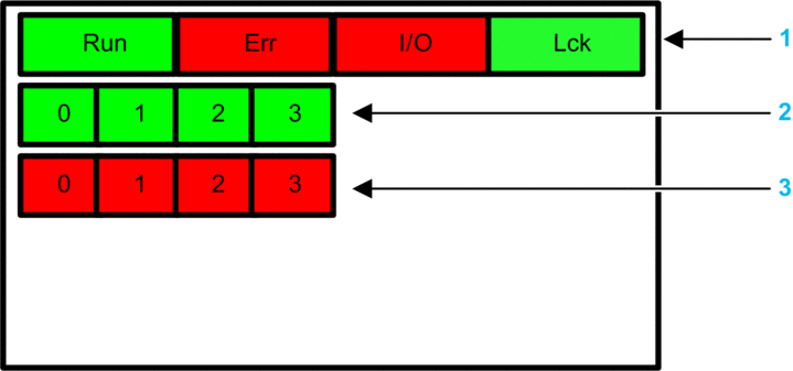
The BMXSAI0410 analog input module presents the following LED panel on its front face:

1 Module state LEDs
2 Channel state LEDs
3 Channel detected error LEDs
The channel detected error LEDs are operational only after the module has been properly configured. When a channel error is detected, the corresponding LED remains ON until the underlying condition is resolved.
Because the input module includes only four channels, LEDs in positions 4...7 are not used and are never powered on.
Module Diagnostics
Use the four LEDs at the top of the LED panel to diagnose the condition of the BMXSAI0410 analog input module:
Module LEDs |
Module State |
Recommended Response |
|||
|---|---|---|---|---|---|
Run |
Err |
I/O |
LCK |
||
Blinking1 |
Blinking1 |
Blinking1 |
Blinking1 |
Auto-test at power-on. |
– |
Blinking1 |
ON |
OFF |
Blinking1 |
Auto-test at power-on has detected an internal error on input channels. |
Replace the module. |
OFF |
ON |
OFF |
OFF |
Internal error detected. |
Replace the module if the condition persists. |
OFF |
Blinking1 |
OFF |
X |
Non-configured I/O module. |
Configure the module via the CPU. |
X |
X |
ON |
X |
External error detected on input channel. |
Refer to Channel Diagnostics (below). |
ON |
Blinking1 |
X |
X |
No communication between CPU and I/O module. |
Verify that:
|
ON |
Flickering2 |
X |
OFF |
Communication not safe and configuration unlocked. |
Debug the condition using the DDDT variables for the I/O module instance. |
ON |
Flickering2 |
X |
ON |
Communication not safe and configuration locked. |
Verify that:
|
ON |
ON |
OFF |
X |
Input channel Internal error detected |
Replace the module if the condition persists. |
ON |
OFF |
OFF |
OFF |
Communication with CPU is OK and the configuration is unlocked. |
– |
ON |
OFF |
OFF |
ON |
Communication with CPU is OK and the configuration is locked. |
– |
X indicates the LED state can be either ON or OFF. 1. Blinking: 500 ms ON / 500 ms OFF. 2. Flickering: 50 ms ON / 50 ms OFF. |
|||||
Channel Diagnostics
Use all the LEDs on the BMXSAI0410 analog input module to diagnose channel status:
Module LEDs |
Channel LEDs |
Channel State |
Recommended Response |
||||
|---|---|---|---|---|---|---|---|
Run |
Err |
I/O |
LCK |
Channel State (LED 0...3) |
Detected Error (LED 0...3) |
||
ON |
OFF |
Off |
X |
ON |
OFF |
The input current is in the range 4...20 mA on the channel. |
– |
ON |
OFF |
ON |
X |
OFF |
OFF |
The input current is out of the range 4...20 mA on the channel. |
Verify that the external power-supply, the external cabling, and the sensor are operational. |
ON |
ON |
OFF |
X |
OFF |
ON |
The channel is not operational. |
Replace the module if the condition persists. |
X indicates the LED state can be either ON or OFF. |
|||||||


