|
|
Original instructions
|

|
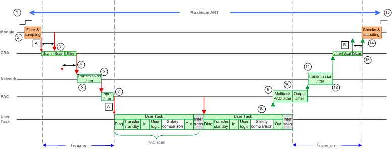
A: missed input scan
|
8: operation of application logic (1 scan)
|
|
B: missed output scan
|
9: additional jitter due to the PAC multitasking
|
|
1: input turns ON
|
10: CPU output jitter
|
|
2: input filtering and sampling (Safe modules)
|
11: network delay
|
|
3: CRA drop processing time
|
12: network jitter
|
|
4: CRA input request packet interval (RPI) rate
|
13: CRA drop processing time
|
|
5: network delay
|
14: output check and actuating (Safe modules)
|
|
6: network jitter
|
15: output applied
|
|
7: CPU input jitter
|
ľ
|
|
Name
|
Description
|
Value
|
|
|---|---|---|---|
|
TINPUT
|
Time used by the safety input modules for the filtering and the sampling of the external signal.
|
6áms
|
|
|
TCOM_IN
|
Sum of all the time used by the communication with input modules.
|
See1
|
|
|
Lost_scan
|
Lost scan time because the input message arrived too late, after the begin of the scan.
|
TPER2
|
|
|
Eff_scan
|
Effective scan which computes the outputs depending on the latest sampled input value.
|
TPER2
|
|
|
Multitask_jitter
|
Jitter introduced by the multi-task system on the output message emission. The real value is based on the task execution time, for simplification they are capped by the task period.
|
Mast task
|
TSAFE3 + TFAST3
|
|
Safe task
|
TFAST3
|
||
|
Fast task
|
0
|
||
|
TCOM_OUT
|
Sum of all the time used by the communication with output modules.
|
See1
|
|
|
TOUTPUT
|
Time used by the safety output modules for the diagnostics and for actuating the external signal.
|
6áms
|
|
|
1. For a description of these elements, refer to the more complex ART calculation method in the Modicon M580 Standalone System Planning Guide for Frequently Used Architectures.
2. Refer to the Processor Load topic for a discussion of these elements.
3. The configured cycle period for the respective task (SAFE, FAST).
|
|||

|
Name
|
Description
|
Value
|
|
|---|---|---|---|
|
TINPUT
|
Time used by the safety input modules for the filtering and the sampling of the external signal.
|
6áms
|
|
|
TCOM_IN
|
Sum of all the time used by the communication with input modules.
|
See1
|
|
|
Lost_scan
|
Lost scan time because the input message arrived too late, after the begin of the scan.
|
TPER2
|
|
|
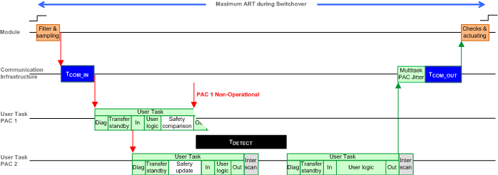
TDETECT
|
Time used by the standby PAC to detect and confirm the primary PAC has become non-operational.
|
15áms
|
|
|
Eff_scan
|
Effective scan which computes the outputs depending on the latest sampled input value.
|
TPER2
|
|
|
Multitask_jitter
|
Jitter introduced by the multi-task system on the output message emission. The real value is based on the task execution time, for simplification they are capped by the task period.
|
Mast task
|
TSAFE3 + TFAST3
|
|
Safe task
|
TFAST3
|
||
|
Fast task
|
0
|
||
|
Additional_jitter
|
Jitter introduced by the multi-task system to restart the task on the new PAC.
|
Mast task
|
0
|
|
Safe task
|
TSAFE3
|
||
|
Fast task
|
TFAST3
|
||
|
TCOM_OUT
|
Sum of all the time used by the communication with output modules.
|
See1
|
|
|
TOUTPUT
|
Time used by the safety output modules for the diagnostics and for actuating the external signal.
|
6áms
|
|
|
1. For a description of these elements, refer to the more complex ART calculation method in the Modicon M580 Standalone System Planning Guide for Frequently Used Architectures.
2. Refer to the Processor Load topic for a discussion of these elements.
3. The configured cycle period for the respective task (SAFE, FAST).
|
|||

|
Name
|
Description
|
Value
|
|
|---|---|---|---|
|
TINPUT
|
Time used by the safety input modules for the filtering and the sampling of the external signal.
|
6áms
|
|
|
TCOM_IN
|
Sum of all the time used by the communication with input modules.
|
See1
|
|
|
Lost_scan
|
Lost scan time because the input message arrived too late, after the begin of the scan.
|
TPER2
|
|
|
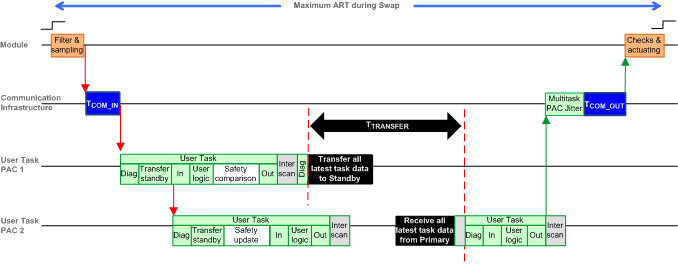
TTRANSFER
|
During the diagnostics of the MAST task, the PAC accepts the Swap command and begins to perform the transfer of all the latest data for each task.
|
Refer to the formula, below.
|
|
|
Eff_scan
|
Effective scan which computes the outputs depending on the latest sampled input value.
|
TPER2
|
|
|
Multitask_jitter
|
Jitter introduced by the multi-task system on the output message emission. The real value is based on the task execution time, for simplification they are capped by the task period.
|
Mast task
|
TSAFE3 + TFAST3
|
|
Safe task
|
TFAST3
|
||
|
Fast task
|
0
|
||
|
Additional_jitter
|
Jitter introduced by the multi-task system to restart the task on the new PAC.
|
Mast task
|
0
|
|
Safe task
|
TSAFE3
|
||
|
Fast task
|
Min(TFAST, 5áms)3
|
||
|
TCOM_OUT
|
Sum of all the time used by the communication with output modules.
|
See1
|
|
|
TOUTPUT
|
Time used by the safety output modules for the diagnostics and for actuating the external signal.
|
6áms
|
|
|
1. For a description of these elements, refer to the more complex ART calculation method in the Modicon M580 Standalone System Planning Guide for Frequently Used Architectures.
2. Refer to the Processor Load topic for a discussion of these elements.
3. The configured cycle period for the respective task (SAFE, FAST).
|
|||
|
Coefficient
|
BMEH582040S
|
BMEH584040S or BMEH586040S
|
|---|---|---|
|
K3
|
46.4
|
14.8
|
|
K4
|
34.5
|
11.0
|