Sub-Ring Diagnostics
Original instructions
Detecting a Sub-ring Break via DRS
This topic describes how to detect a cable break in a sub-ring on the RIO network by diagnosing a DRS.
Step
Action
1
Write a DATA_EXCH block to the DRS managing the sub-ring of interest.
NOTE: Use the CPU with Ethernet I/O scanner service to send DATA_EXCH commands to diagnose the status of sub-rings. For other operations (get remote statistics, read data, etc.), we recommend that you send a DATA_EXCH command from a communication module on the local rack.
2
Read the states of ports 5 and 6 on the DRS. The possible port state values are:
1 
disabled
2 
blocking
3 
listening
4 
learning
5 
forwarding
6 
broken
3
  • If either port 5 or 6 is in a blocking state (2), then the loop is present and healthy (no cable break.)
  • If both ports 5 and 6 are in any other state besides blocking state (2), then there is a cable break on the sub-ring.
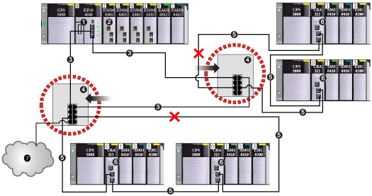
This graphic shows breaks in 2 sub-rings connected by DRSs on the main ring. The arrows point to the DRSs, on which you monitor ports 5 and 6 in your application using a DATA_EXCH block:
1 
CPU with Ethernet I/O scanner service on the local rack
2 
BMENOC0301/11 Ethernet communication module (with the Ethernet backplane connection enabled), managing the DIO cloud (7)
3 
main ring
4 
DRS connected to the main ring and RIO sub-rings
5 
RIO sub-ring with a communication break (indicated by an X)
6 
RIO drop (including a BM•CRA312•0 X80 EIO adapter module)
7 
DIO cloud connected to a DRS
NOTE: When you add or remove devices from your network configuration, modify the sub-ring cable break logic in your application.
Writing a DATA_EXCH Block to Diagnose a Sub-ring Break
This is an example of a DATA_EXCH block created in a Control Expert application to read the DRS ports 5 and 6 state.
In the Control Expert application, write a DATA_EXCH block to send an EIP explicit message to the DRS that is managing the sub-ring. This EIP explicit message can be sent via the BM•CRA312•0 module or other communication module that is managing devices in the device network.
NOTE: Use a CPU with Ethernet I/O scanner service to send DATA_EXCH commands to diagnose the status of sub-rings.
To create the DATA_EXCH block, create and assign variables, and connect the block to an AND block. The logic continuously sends an explicit message when it receives confirmation of success or detected error.
Refer to the Explicit Messaging topic in the Modicon M340 BMX NOC 0401 Ethernet Communication Module User Manual for details on using the DATA_EXCH block.
Input Parameters
Create variables and assign input pins. In this example, variables have been created (and named) as described below. (You can use different variable names in your explicit messaging configurations.)
Parameter
Data Type
Description
Array [0...7] of INT
The path to the DRS. Use the ADDM function.
ActionType
INT
The type of action to perform. The setting = 1 (transmission followed by await reception).
Array [n...m] of INT
Input/Output Parameters
Create variables and assign input pins. In this example, variables have been created (and named) as described below. (You can use different variable names in your explicit messaging configurations.)
Parameter
Data Type
Description
Array [0...3] of INT
consists of 4 words
Output Parameters
Create variables and assign output pins. In this example, variables have been created (and named) as described below. (You can use different variable names in your explicit messaging configurations.)
Parameter
Data Type
Description
Array [n...m] of INT
the EtherNet/IP (CIP) response