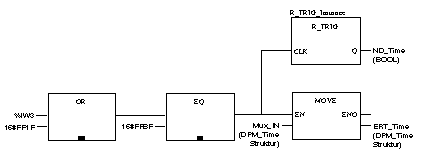
This section presents an internal function which is made available through the ERT for diagnostics and development. It covers the cyclic transfer of the ERT internal time to the corresponding EFB in greater intervals. This time application can be used to display or set the PLC clock etc, regardless of whether it comes from the free-running internal clock or was synchronized through an external reference clock signal. The time appears as a DPM_Time structure beginning with word 4 of the IN register block of the ERT. The following diagram shows the program elements involved in selection.
Commissioning information
A ERT_854_10 was assigned the IN references %IW1 ... . %IW3 during I/O addressing. The IN transfer status (TS_IN) in the third word of the register block is sent to an OR block. A DPM_Time structure is defined within the variable editor as Variable Mux_IN in the fourth word of the IN register block, and therefore has the address %IW4 ... %IW7. This variable is sent to the MOVE block as an entry. The MOVE block output is a DPM_Time structure defined by the variable editor as variable ERT_Time.
Typical recording mechanism for ERT time data
NOTE: The ERT_854_10 EFB must be active and error free.
The MOVE block transfers the time data cyclically stored in the MUX zone of the IN register block to the DPM_Time structure ERT_Time belonging to the user as soon as the OR and the EQ block signals a time data transfer. R_TRIG makes a signal in ND_Time available for further processing of the time data available for one cycle. The BOOL Sync element value of the ERT_Time should begin to "tick" during each new transfer from the ERT. There is a new transfer after a maximum of each 200 PLC cycles.
