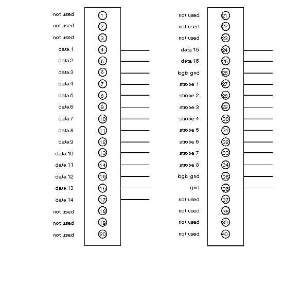
Terminal Numbering and Output Functions
User connections are made to a standard screw terminal strip. The rigid wiring system permits module insertion or removal without disturbing the wiring.
The following illustration shows how to field connect the unit.
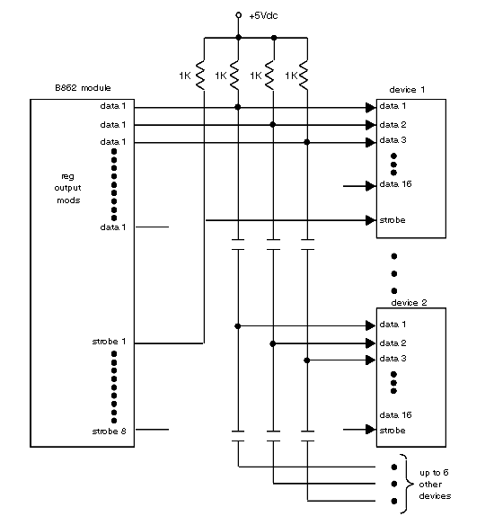
Pull-up Resistor Connection
Pull-up resistors must be installed at the active device end to use the B862 output module. The value of the pull-up resistor depends upon the number of devices that are attached to the data bus, as explained below. Each output meets 0.4 V maximum at 16 mA for a logic low and 3.3 V minimum at 16 mA for a logic high. If the current limit has been exceeded, the pull-up resistor values should be adjusted within specification; otherwise, spurious results may be obtained.
The following illustration indicates how the resistors are connected at the device end. For a single device consisting of 16 data lines, 16 1 k resistors are required, or, one 1 k resistor per data line. As additional devices are added to the data bus, the value of the pull-up resistor must be increased by 1 k. In other words, if two devices are used, the pull-up resistor must be 2 k, three devices require a 3 k pull-up, and so on, with the maximum number of 8 devices requiring 8 k of pull-up for each data line.
Pull-up resistor connection
NOTE: Increase pull-up resistor value by 1 k for each additional device.