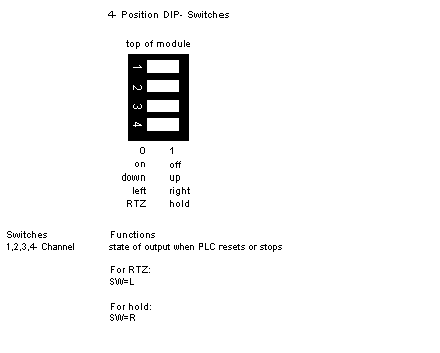
The four position DIP-switch is located on the rear of the module. This switch controls the state of each channel when the system is reset or stopped. The output to the channel can either remain at the last value (Hold) or go to 0.0 mA Return-To-Zero (RTZ).
Set the switch for either hold or RTZ prior to installation of the module. Each of the four switches control the mode of operation for its associated output (i.e., switch 1 for output 1, etc.). Refer to the figure below for switch settings. Also, refer to the label located on the left side of the module itself.
The following figure gives DIP-Switch Settings for the B872-200 module.
Set the switch to the left to select return-to-zero or to the right to select hold (viewing the rear of the module when held vertically). Channels are set independently.
NOTE: The output state after power-up initialization is dependent on the position of DIP-switch. Open circuit in the following table results in current 0 mA.
The following table shows the relationship between power-up & DIP-switch settings.
Possible Event During Power-up
|
Switch=RTZ
|
Switch=HOLD
|
At Power-up
|
0 Volts*
|
0 Volts*
|
After Receiving Valid Data
|
Data
|
Data
|
PC Stop (After Run)
|
0 Volts*
|
Last Data
|
Loss of +5 V
|
0 Volts*
|
0 Volts*
|
Loss of +4.3 VIO
|
0 Volts*
|
Last Data
|
Loss of +5 V & +4.3 VIO
|
0 Volts*
|
0 Volts*
|
*Active circuits of module are disconnected from the output terminals, the output terminals are connected to an internal 100 Ω resistor.
|