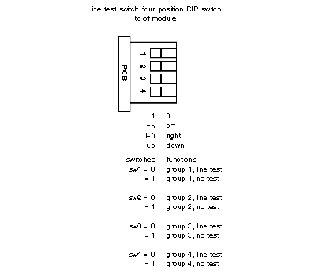
A four–position DIP switch located on the rear of the module (see diagram below) is used to select broken wire testing. Each individual switch relates to one of the four groups of eight input points.
For example, DIP-Switch position #1 when set to off senses for broken wire faults for group 1 and so on; when set to on no fault is reported.
Only Binary should be used when operating module in line test mode. Do not use BCD.
The line test dip-switch settings are shown below.
NOTE: When using binary and BCD inputs remember that input 1 is the MSB and input 32 is the LSB.
