|
B855–016 Intrinsically Safe Input, Installation
|
|


|
(Original Document)
|
|
B855–016 Intrinsically Safe Input, Installation
|
|
|
(Original Document)
|
|
Step
|
Procedure
|
|---|---|
|
1
|
Remove the module from its shipping box and check for damage. If damaged, contact your vendor for instructions.
|
|
2
|
Ensure power to housing is off.
|
|
3
|
Designate the housing slot for this module.
|
|
4
|
Locate required connector assembly (Part number AS-8535-000). This assembly consists of two 20-pin connectors.
|
|
5
|
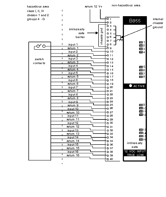
Referring to the hazardous area and safe area wiring diagram below, connect field side wiring to proper pins on the field connector. You must wire the hazardous area connections, pins 9-40, separately from the safe area connections. Wire the dc source to the safe area connections, pins 1 and 2. Refer to Caution, below.
|
|
6
|
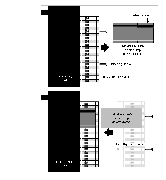
Refer to the intrinsically safe barrier strip diagram below. Remove the two Phillips head screws from the top 20-pin connector of the AS-8535-000. Take the intrinsically safe barrier strip out of the white bag attached to the handle of the module. Place the intrinsically safe barrier strip on the left side of the top 20-pin connector between pins 3, and 8. Make sure the raised edge of the intrinsically safe barrier strip is facing away from the black wiring duct. Insert this subassembly inside the black wire duct while aligning the two screw holes. Insert the two Phillips head screws and tighten them down. Note: You must use key pins (shipped with this module) to meet factory mutual’s requirements.
|
|
7
|
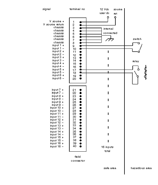
Referring to typical field circuit connections illustration, below, connect field side wiring to proper pins on the field connector. Note: The external 12 Vdc (5%) power supply for the module should be a minimum of 1.0 A
|
|
8
|
Insert the module into the housing, firmly but carefully, seating the edge connector in the backplane.
|
|
9
|
Secure module to housing using captive slotted mounting screws at the top and bottom of the module front panel.
|
|
10
|
Note:
To meet factory mutual’s requirements, Schneider Electric recommends the MD-8741-000 intrinsically safe barrier strip.
|