The B865–001 register input module provides a 5 V TTL or CMOS-compatible interface between peripheral field devices and a PLC.The B865-001 is an eight-channel register module with eight 16-bit registers. A channel is defined as a 16-bit data path.
The module can operate in either BCD or binary mode. The desired mode is user-selectable, with the parallel 16-bit input having BCD values in the range 0000- 9999 and the binary input in the range0000-FFFF.
The B865–001 operates in module-select mode, which updates the controller with eight input registers of new data samples on one scan period. The module-select feature ensures data integrity by sampling and comparing data from the user device twice during each channel’s active strobe period. If the samples are equal, the data is accepted for further processing. If the samples are not equal, the old data is sent to the controller. If a channel has three consecutive no-compares, a 16-bitword containing all zeros is routed to the PLC.
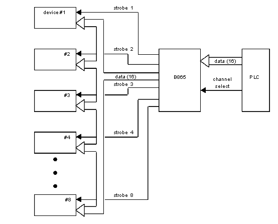
The following diagram shows the schematic diagram for the B865–001 register input module.
The B865–001 operates with a 16-bit data path. Data is routed from a device by means of a strobe line associated with each device. The datalines are common to all devices while the strobe performs the addressing function.
The DC (data changing) signal from the field device is used for slowly changing data such as thumb wheel switches, and prevents erroneous information from being transferred to the PLC. This input needs only be used for slowly changing data that may cause the capture of erroneous information. The DC input connection is made on terminal 18 of the module’s field side wiring strip.
