The default behavior of the Quantum Safety PLC is to perform Safety Functions to achieve and to maintain the Safe state of a process. Nevertheless, you must be able to debug and to maintain your project.
Use the Safety Mode to control your process and the Maintenance Mode for debugging and refining your project.
In Maintenance Mode, the I/O and CPU modules are still executing the diagnostics and establishing the Safe state if a fault is detected. Only the application program and the application data, which may be changed in Maintenance Mode, are not checked.
NOTE: To program a Quantum Safety PLC, Unity Pro 7.0 XLS is required.
Safety and Maintenance Mode Features
The operating mode of the Quantum Safety PLC depends on events such as application exception, power on/off, and so on. The functions available in Unity Pro XLS depend on the operating mode.
Switching between the modes requires defined conditions and follows certain procedures. For details, see the chapter Switching Between Safety and Maintenance Mode in Unity Pro XLS Software, Operating Mode Manual, Safety PLC Specifics.
You can interact with the Safety PLC using:
-
Unity Pro XLS programming tool
-
Quantum Safety CPU keypad
-
Quantum Safety CPU key switch
Depending on the operating mode, the Safety PLC can be in different states.
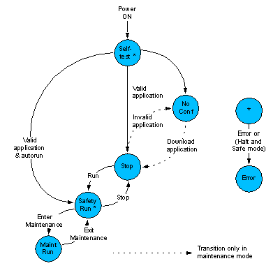
After power up, it automatically enters run state of the Safety Mode if the following 2 conditions are fulfilled:
In case of an invalid application, it enters the not configured (no conf) state of the Maintenance Mode (only if the key state is unlocked), in which you are able to download your project.
If a fault is detected, the PLC enters
The following figure shows the state diagram of the Quantum Safety PLC:
Operating Mode Identification
The LCD display on the CPU indicates the current operating mode by showing the letters M for Maintenance Mode or S for Safety Mode.
The status bar field on the PLC screen indicates the current operating mode as shown in the following figure:

