|
|
Original instructions
|


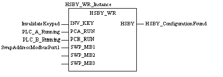
CAL HSBY_WR_Instance (INV_KEY:=InvalidateKeypad,
         PCA_RUN:=PLC_A_Running, PCB_RUN:=PLC_B_Running,
         SWP_MB1:=SwapAddressModbusPort1,
         HSBY=>HSBY_ConfigurationFound)
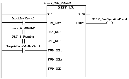
HSBY_WR_Instance (INV_KEY:=InvalidateKeypad,
         PCA_RUN:=PLC_A_Running, PCB_RUN:=PLC_B_Running,
         SWP_MB1:=SwapAddressModbusPort1,
         HSBY=>HSBY_ConfigurationFound);
|
Parameter
|
Data type
|
Meaning
|
|---|---|---|
|
INV_KEY
|
In the submenu for the Hot Standby PLC button:
1 = Changes are not allowed.
0 = Changes are allowed.
|
|
|
PCA_RUN
|
BOOL
|
If 1 -> 0, then the Hot Standby ‘A’ CPU on the local rack is forced into OFFLINE mode.
If 0 -> 1 and its button mode is in RUN mode, then the Hot Standby ‘A’ CPU is forced into the RUN mode.
|
|
PCB_RUN
|
BOOL
|
If 1 -> 0, then the Hot Standby ‘B’ CPU on the local rack is forced into OFFLINE mode.
If 0 -> 1 and its button mode is in RUN mode, then the Hot Standby ‘B’ CPU is forced into the RUN mode.
|
|
SWP MB1
|
BOOL
|
If 0 and there is a Switchover, then the Modbus address on port 1 of the NEW Primary CPU PLC changes:
|
|
If 1 and there is a Switchover, then the Modbus address on Port 1 of the PLC does not change:
|
||
|
SWP_MB2
|
BOOL
|
Not used. Reserved
|
|
SWP MB3
|
BOOL
|
Not used. Reserved
|
|
Parameter
|
Data type
|
Meaning
|
|---|---|---|
|
HSBY
|
BOOL
|
1 = Hot Standby configuration found.
0 = Hot Standby configuration not found.
|