After reviewing the MAST task execution modes, this topic describes adjusting the MAST task period and execution time measurement procedures.
Review of MAST Task Execution Modes
The MAST task can be configured to use one of two execution modes:
-
Cyclic mode:
In the cyclic execution mode, MAST tasks occur in sequence with no reference to the system clock without any delay between tasks other than a very brief period of system processing. Almost immediately after one task completes another begins. Therefore, the actual duration of a MAST task in the cyclic mode can vary significantly depending on the size and activity of the application, and the number of inputs and outputs to be controlled.
-
Periodic mode:
In the periodic execution mode, MAST tasks are sequenced according to a countdown timer which is referenced to the system clock. This countdown timer may be set for a period between 1 and 255 ms. If the countdown expires before the end of the task, the task completes normally. If this occurs regularly, the system will appear as if the cyclic MAST task execution mode had been selected. However, some applications, such as process control, do require regular cycle times. If this is the case for your application, confirm that the task period is of sufficient length to avoid cyclic-like behavior.
Execution Time Measurement
The execution time of the MAST task can be measured by reading system words:
-
%SW30: Execution time (in ms) of the last task
-
%SW31: Execution time (in ms) of the longest task
-
%SW32: Execution time (in ms) of the shortest task
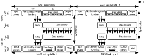
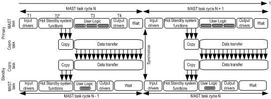
In both cyclic and periodic mode, the MAST execution time is the sum of T1 + T2 + T3 + T4.
T5 of the periodic mode is not taken into account.
First Step of Execution Time Measurement
To measure the execution time of the MAST task in a Quantum Hot Standby configuration, it is advised to measure first the execution time in standalone mode (or with one of the two PLC in STOP) with the MAST task configured in cyclic mode. In this case, there is no data exchange between the two PLCs, and the execution time of the Hot Standby Copro part (T2) is reduced to its minimum.
The execution time of the last MAST cycle = %SW30 = T1 + T2 + T3 + T4.
Second Step of Execution Time Measurement
In a second step, the execution time has to be measured with a Primary and Standby PLC.
Two cases have to be taken into account:
-
The data transfer has no impact on the Primary MAST task duration:
In this case, the execution time of the Hot Standby part (T2’) is increased with the time required to copy the data base from the CPU memory to the Hot Standby Copro shared memory.
The execution time of the last MAST cycle = %SW30 = T1 + T2’ + T3 + T4 with T2’ = T2 + time to copy the data base from the CPU memory to the Copro shared memory.
There is no need for a Wait state to be added to the Primary MAST task because the User Logic “covers” the Copro data transfers.
-
The data transfer has an impact on the Primary MAST task duration:
In this case, the time to copy to the Copro shared memory, increases T2" compared to T2.
Also, because of the increased data, the data transfer between the Primary and Standby Copros requires a Wait state in the Primary MAST task.
The execution time of the last MAST cycle = %SW30 = T1 + T2’’ + T3 + T4 + Wait state where T2’’ = T2 + time to copy the data base from the CPU memory to the Copro + time to transmit all the data on the network and free the Copro shared memory.
Third Step of Execution Time Measurement
In the periodic mode, it appears that the execution time that is measured is lower than in the cyclic mode. In certain cases, the difference between the two execution modes can be large.
Procedure to Adjust MAST Task in Periodic Mode
If the MAST task has to be configured in the periodic mode, it is recommended to:
|
Step
|
Action
|
|
1
|
Measure the maximum value (%SW31) of the MAST task in cyclic mode with the Quantum Hot Standby Primary and Standby PLCs) running normally.
This measure has to be done in the Primary PLC with all the configured tasks active (only the MAST task is recommended in a Quantum Hot Standby application).
|
|
2
|
Configure the periodic mode with a period at least equal to %SW31 plus a margin of around 20%, that is, Period = %SW31 + (%SW31 * 20%).
|
 WARNING


