Schneider Electric Recommends
Recommendations:
-
For 140 CPU 67• 60 modules, use up to 4 km (2.5 mi) of 62.5/125 µm, graded index, duplex, multi mode glass fiber (usually referred to as OM1 type fiber).
This type of fiber is rated at maximum attenuation of 1.5 dB per km (maximum, at 1300 nm).
-
For 140 CPU 67• 61 modules, use up to 16 km (9.9 mi) of 9/125 µm, duplex, single mode glass fiber (usually referred to as OS1 or G652 type fiber).
This type of fiber is rated at maximum attenuation of 0.35 dB per km (maximum, at 1300 nm).
-
Wherever possible, use a multifiber cable since the cable is less expensive and provides a backup in case one of the fibers is cut during installation.
Typical Configuration Scheme
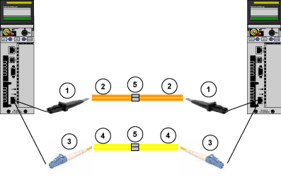
The following figure represents the direct connection with splices between two CPUs:
Explanation of direct connections above:
-
MTRJ connector
-
Duplex 62.5/125 µm, graded index, multi-mode fiber optic cable
Use only single mode with 140 CPU 67• 60: up to 4 km (2.5 mi).
-
LC connector
-
Duplex 9 / 125 µm, single-mode fiber optic cable
Use only single mode with 140 CPU 67• 61: up to 16 km (9.9 mi).
-
Splices
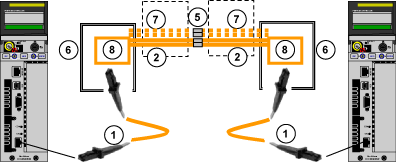
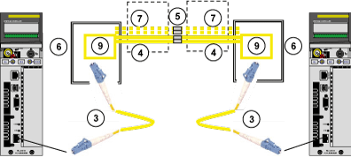
The following figures represent the direct connection with splices between two modules when using a multi-fiber cable:
Multimode (140 CPU 67• 60 CPUs): up to 4 km (2.5 mi)
Single mode (140 CPU 67• 61 CPUs): up to 16 km (9.9 mi)
Explanation of direct connections above:
-
MTRJ/MTRJ fiber connector
-
Duplex 62.5/125 µm, graded index, multi-mode fiber optic Cable
-
LC/LC fiber connector
-
Duplex 9/125 µm, single-mode fiber optic Cable
-
Splices
-
Fiber distribution box
-
Backup fiber
-
MTRJ jack (or MTRJ coupler)
-
LC jack (or LC/LC coupler)
Optical Power Budget Calculation
The maximum length of Hot Standby fiber optic link must be calculated by considering total loss in all components used in the path, fiber optic cable, optical connectors and splices:
-
For 140 CPU 67• 60 PLCs, the Power Loss Budget in 62.5/125 µm fiber cable equals 9.9 dB (including system margin).
-
For 140 CPU 67• 61 PLCs, the Power loss Budget in 9/125 µm fiber cable equals 9 dB (including system margin)
NOTE: There is no minimum distance requirement.
The fiber optic cables are sold separately:
|
Multi mode Models for 140 CPU 67• 60
|
Description
|
|
490NOR00003
|
3 m MTRJ/MTRJ
|
|
490NOR00005
|
5 m MTRJ/MTRJ
|
|
490NOR00015
|
15 m MTRJ/MTRJ
|
|
Single mode Models for 140 CPU 67• 61
|
|
|
VDIF0646463505
|
5 m LC DUPLEX / LC DUPLEX - Simple CPU to CPU connection
|
|
VDIF0646463505
|
5 m SC DUPLEX / LC DUPLEX - PC to CPU connection1
|
|
1. For firmware upgrade for example. This requires an additional switch: 499NSS25101 (not managed) or TCSESM043F1CS0 (managed).
|


