|
|
Original instructions
|

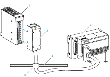
1BMEAHO0412 module
2BMXFCA••0 connecting cables
3Interface sub-base ABE7CPA21
4Shield bar
5Clamp

1BMXFTB2020 Terminal block
2Cable shielding
325-pin Sub-D connector
LLength according to the part number.
|
Characteristic
|
Value
|
|
|---|---|---|
|
Cable
|
Sheath material
|
PVC
|
|
LSZH status
|
No
|
|
|
Environmental
|
Operating temperature
|
-25...70 °C (-13...158 °F)
|
|
TELEFAST terminal block number
|
BMEAHO0412 pinout
|
Signal type
|
TELEFAST terminal block number
|
BMEAHO0412 pinout
|
Signal type
|
|---|---|---|---|---|---|
|
1
|
NC
|
Ground
|
Supp 1
|
NC
|
Ground
|
|
2
|
NC
|
STD(1)
|
Supp 2
|
NC
|
Ground
|
|
3
|
NC
|
STD(1)
|
Supp 3
|
NC
|
Ground
|
|
4
|
NC
|
STD(2)
|
Supp 4
|
NC
|
Ground
|
|
100
|
1
|
CH0
|
200
|
2
|
COM0
|
|
101
|
NC
|
NC
|
201
|
NC
|
Ground
|
|
102
|
7
|
CH1
|
202
|
8
|
COM1
|
|
103
|
NC
|
NC
|
203
|
NC
|
Ground
|
|
104
|
11
|
CH2
|
204
|
12
|
COM2
|
|
105
|
NC
|
NC
|
205
|
NC
|
Ground
|
|
106
|
17
|
CH3
|
206
|
18
|
COM3
|
|
107
|
NC
|
NC
|
207
|
NC
|
Ground
|
|
COMx: Common pin for channel x
NC: Not connected
|
|||||
  DANGER DANGER |
|
HAZARD OF ELECTRIC SHOCK
Confirm that the strap for the ABE7CPA21 is removed.
Failure to follow these instructions will result in death or serious injury.
|

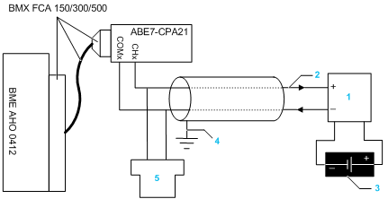
12-wire or 4-wire transmitter
24-20 mA current loop, with arrows indicating direction of current flow
3Field power supply (for 4-wire design only)
4Protective ground
5Secondary HART master (hand-held)