|
Installing Analog I/O Modules
|
|
|
Original instructions
|
  DANGER DANGER |
|
HAZARD OF ELECTRIC SHOCK, EXPLOSION, OR ARC FLASH
Before mounting / removing the modules:
Failure to follow these instructions will result in death or serious injury.
|
|
Backplane
|
Description
|
|---|---|
|
BME XBP 04001
|
4-slot Ethernet backplane
|
|
BME XBP 0400(H)1
|
4-slot hardened Ethernet backplane
|
|
BME XBP 08001
|
8-slot Ethernet backplane
|
|
BME XBP 0800(H)1
|
8-slot hardened Ethernet backplane
|
|
BME XBP 12001, 2
|
12-slot Ethernet backplane
|
|
BME XBP 1200(H)1, 2
|
12-slot hardened Ethernet backplane
|
|
1. The following reserved slots are not available for module installation:
2. The following reserved slots are not available for module installation: slots 2, 8, 10 and 11, which are reserved for gateway communication modules.
|
|

|
Number
|
Description
|
|---|---|
|
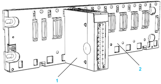
1
|
20-pin terminal block module
|
|
2
|
8 slot Ethernet backplane
|
|
Step
|
Action
|
Illustration
|
|---|---|---|
|
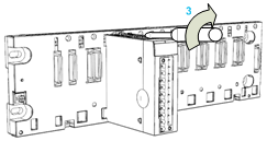
1
|
Position the locating pins situated at the rear of the module (on the bottom part) in the corresponding slots in the rack.
NOTE: Before positioning the pins, remove the protective cover. |
Steps 1 and 2
 |
|
2
|
Swivel the module towards the top of the rack so that the module sits flush with the back of the rack. It is now set in position.
|
|
|
3
|
Tighten the retaining screw to hold the module in place on the rack.
Tightening torque: 0.4...1.5 N•m (0.30...1.10 lbf-ft).
|
Step 3
 |