|
MBP_MSTR Example: Get_Attributes_Single
|
|
|
Original instructions
|

|
Input Pin
|
Variable
|
Data Type
|
|---|---|---|
|
ENABLE
|
Enable
|
BOOL
|
|
ABORT
|
StopEM
|
BOOL
|
|
Output Pin
|
Variable
|
Data Type
|
|---|---|---|
|
ACTIVE
|
EMActive
|
BOOL
|
|
ERROR
|
EMError
|
BOOL
|
|
SUCCESS
|
EMSuccess
|
BOOL
|
|
CONTROL
|
EIP_ControlBuf
|
Array of 10 WORDs
|
|
DATABUF
|
EIP_DataBuf
|
Array of 100 WORDs
|
|
Register
|
Description
|
Configure
|
Setting (hex)
|
|---|---|---|---|
|
CONTROL[0]
|
Operation:
High byte =
Low byte = 0E (CIP explicit message)
|
Yes
|
16#000E (unconnected)
|
|
CONTROL[1]
|
Detected error status: read-only (written by operation)
|
No
|
16#0000
|
|
CONTROL[2]
|
Data buffer length = 100 words
|
Yes
|
16#0064
|
|
CONTROL[3]
|
Response offset: offset — in words — for the beginning of the explicit message response in the databuffer
|
Yes
|
16#0004
|
|
CONTROL[4]
|
High byte = slot location of the communication module in the backplane
Low byte = 0 (not used)
|
Yes
|
16#0400
|
|
CONTROL[5]1
|
IP address of the Ethernet communication module:
High byte = byte 4 of the IP address
Low byte = byte 3 of the IP address
|
Yes
|
16#C0A8
|
|
CONTROL[6]1
|
IP address of the Ethernet communication module:
High byte = byte 2 of the IP address
Low byte = byte 1 of the IP address
|
Yes
|
16#0106
|
|
CONTROL[7]
|
CIP request length (in bytes)
|
Yes
|
16#0008
|
|
CONTROL[8]
|
Length of received response (written by operation)
|
No
|
16#0000
|
|
1. In this example, the control parameter handles the IP address 192.168.1.6 in the following order: Byte 4 = 192, Byte 3 = 168, Byte 2 = 1, Byte 1 - 6.
|
|||
|
Request word
|
High byte
|
Low byte
|
||
|---|---|---|---|---|
|
Description
|
Value (hex)
|
Description
|
Value (hex)
|
|
|
1
|
Request path size (in words)
|
16#03
|
EM Service: Get_Attributes_Single
|
16#0E
|
|
2
|
Request path: class assembly object
|
16#04
|
Request path: logical class segment
|
16#20
|
|
3
|
Request path: instance
|
16#64
|
Request path: logical instance segment
|
16#24
|
|
4
|
Request path: attribute
|
16#03
|
Request path: logical attribute segment
|
16#30
|
|
Request word
|
Value
|
|---|---|
|
1
|
16#030E
|
|
2
|
16#0420
|
|
3
|
16#6424
|
|
4
|
16#0330
|
|
Step
|
Action
|
|
|---|---|---|
|
1
|
In Control Expert, select Tools → Project Browser to open the Project Browser.
|
|
|
2
|
In the Project Browser, right-click Animation Tables → New Animation Table.
Result: A new animation table opens.
|
|
|
3
|
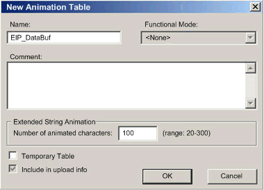
In the New Animation Table dialog, edit the following values:
|
|
|
Name
|
Type in a table name. For this example: EIP_DataBuf.
|
|
|
Functional Mode
|
Accept the default <None>.
|
|
|
Comment
|
Leave blank.
|
|
|
Number of animated characters
|
Type 100, representing the size of the data buffer in words.
|
|
|
4
|
The completed dialog looks like this:
 Click OK to close the dialog.
|
|
|
5
|
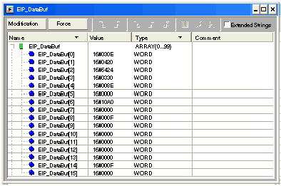
In the animation table’s Name column, type in the name of the variable assigned to the databuffer: EIP_DataBuf and press Enter. The animation table displays the EIP_DataBuf variable.
|
|
|
6
|
Expand the EIP_DataBuf variable to display its word array, where you can view the CIP response at words EIP_DataBuf(7-16):
 Note: Each word presents 2 bytes of data in little endian format, where the least significant byte is stored in the smallest memory address. For example, ‘0E’ in EIP_DataBuf[0] is the low byte, and ‘03’ is the high byte.
|
|