How Taps Have to Be Terminated
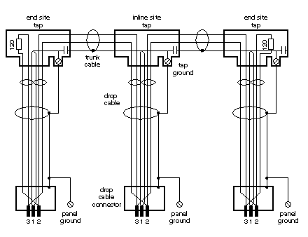
A tap is required at each site on the trunk cable to provide connections for the trunk cable and drop cable. Each tap contains an internal terminating resistor that can be connected by two jumpers. Two jumper wires are included in the tap package, but are not installed. At the taps at the two ends of a cable section, you must connect both of the jumpers to provide the proper terminating impedance for the network. Taps at inline sites must have both jumpers removed. The impedance is maintained regardless of whether a node device is connected to the drop cable. Any connector can be disconnected from its device without affecting the network impedance.
The diagram shows a Modbus Plus Network connection with terminating resistors and grounding.
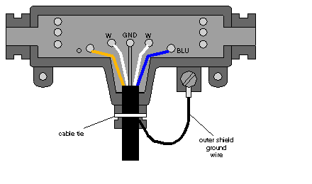
Each tap has a grounding screw for connection to the site panel ground. Schneider Electric drop cables have a grounding lug in the cable package. This must betightly crimped or soldered on the cable and connected to the grounding screw on the tap.
The diagram shows a drop cable, connected and grounded with a tap.
The node device end of the drop cable has a lug which must be connected to the node device’s panel ground. The network cable must be grounded through this connection at each node site, even when the node device is not present. The ground point must not be left open. No other grounding method can be used.
Grounding at the Device Panel
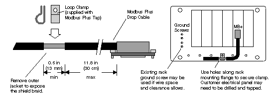
Modbus Plus network drop cables require a ground connection to the rack. The connection is made by means of a metal loop clamp that grounds the cable shield to the ground point.
The following figure shows the Modbus Plus grounding at the device panel.
NOTE: To maintain CE compliance with the European Directive on EMC (89/336/EEC), the Modbus Plus drop cables must be installed in accordance with these instructions.
Preparing the Cable for Grounding
This table shows the steps to prepare the cable for grounding
|
Step
|
Action
|
|
1
|
Determine the distance from the cable´s end connector to the intended ground point on your rack or panel
|
|
2
|
Stripping of the cable´s outer jacket
Note: Keep in mind, that the maximum allowable distance from the ground point to the cable´s end connector is 11.8 in (30 cm)
|
|
3
|
Remove 0.5 -1 in (13-25 mm) of the cable´s outer jacket to expose the shield braid as shown in the figure above. )
|
|
4
|
If the panel has a suitable ground point for mounting the cable clamp, install the clamp at that point
|


