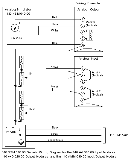
The following diagram shows a typical connection between the simulator, a 140 ACI 030 00 input module and a 140 ACO 020 00 output module. The simulator provides a variable 4 ... 20 mA input to the input module. The input can then be read by a Quantum CPU, and, if required, sent to an output module. For the output module to operate properly, the main current loop must be active, with 24 VDC supplied between terminals 9 and 10 with a 249 Ω voltage drop resistor.
