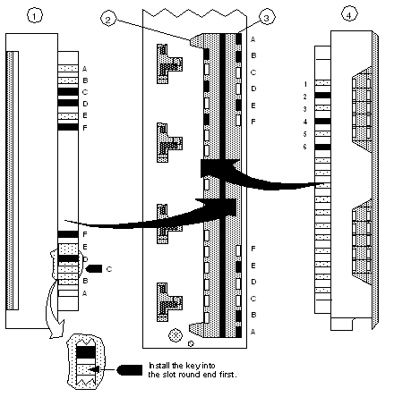
The following figure shows the I/O module and the terminal strip.
1
Right side of Terminal Strip
2
Secondary Key Slots
3
Primary Key Slots
4
Left side of Terminal Strip
NOTE: The primary / secondary keys shown (in black) in this example reflect the recommended coding of a 24 VDC module in slot 6 to its field wiring terminal strip.
To support keying, I/O modules accepting terminal strips come with 12 customer-installable primary keys (six yellow keys each for the module and terminal strip) and six secondary keys (three white keys each for the module and terminal strip). In the following table, check the Primary Module and Terminal Strip Coding columns for key locations.
To implement the user-optional secondary keying code (designed to help prevent the mismatching of terminal strips to I/O modules of identical type), 17 slot positions have been provided in modules and terminal strips to support a variety of coding schemes.
In addition (by using the secondary keying code), the user may key the field wiring terminal to the position where the module is installed in a rack, using the white keys for each code. To determine a unique module code and terminal strip code, refer to the
Primary Keying Table.
