There exists some important design differences between various models of Quantum power supplies that require careful consideration by the system designer in order to achieve maximum system performance. The principal difference lies in the generation within the power supply of important rack signals related to the health of the power supply and the status of the input power.
Quantum power supplies include on-board early power detection logic which is used to signal other modules on the rack that input power is lost. This signal is called POK (power OK) and is active high (i.e., when the signal is high, power is OK).
There is both an internal (to the power supply) and an external (as seen by the rack and other modules) version of the POK signal. The internal POK signal is represented by the Pwr ok LED (light emitting diode) on the front panel of the power supplies.
The system POK signal is generated so that there is sufficient time between the negative going edge of system POK (power outage) and the actual interruption of power to the rack. This first notification of power lost is necessary for the Quantum executive to perform an orderly system shutdown.
Standalone Power Supplies
Four models of standalone power supplies are offered:
|
Power Supply
|
Range
|
Bus Current
|
|
140 CPS 111 00
|
115/230 Vac
|
3 A(60°C)
|
|
140 CPS 114 00
|
115/230 Vac
|
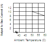
Operating curve:
|
|
140 CPS 211 00
|
24 Vdc
|
3 A(60°C)
|
|
140 CPS 511 00
|
125 Vdc
|
3 A(60°C)
|
The following figure shows the direction of the internal POK to the Quantum system POK.
Four summable power supply models are offered:
|
Power Supply
|
Range
|
Bus Current
|
|
140 CPS 114 10
|
115/230 Vac
|
8 A (60°C)
|
|
140 CPS 114 20
|
115/230 Vac
|
11 A (60°C)
|
|
140 CPS 214 00
|
24 Vdc
|
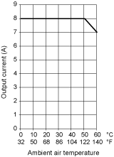
Operating curve:
|
|
140 CPS 414 00
|
48/72 Vdc
|
Operating curve:
|
A summable power supply may be used as a standalone power supply without reservation in any Quantum system.
For systems configured with a mix of CPS, NOM, expert, and l/O modules, whose total current consumption from the rack exceeds the current provided by one summable supply, two summable supplies may be used in a single rack. In such a system, the total current available on the rack is the sum of the capability of both supplies (i.e., 2 x 8 A = 16 A). The summable supplies are designed so that they split the current supplied to the load almost equally, which also has the added benefit of increasing total system MTBF, and to distribute the thermal load across the rack. Summable supplies should be installed in the end module positions in the Quantum rack to maximize the system thermal performance.
The Quantum system POK signal in systems powered by two summable power supplies is only true (power is OK) when both internal POK signals (in the 140 CPS •14 •0) are true. Quantum summable power supplies are not hot-swappable.
The following figure shows the direction of the Quantum POK summable power supplies.
The proper method for starting systems powered by summable power supplies is to insert both supplies in the rack in an unpowered state, and then apply power to each supply. There is no requirement to turn on each supply simultaneously. The system designer must realize that the operation of the summable supply described above is independent of total rack load, i.e., even if the total load on the rack is less than 8 A, if there are two summable supplies installed in the rack, the system POK is generated as shown in this section.
For the special case of a single summable supply used as a standalone, the system POK generation reverts to the standalone case as shown previously in this section.
Five redundant power supply models are offered:
|
Power Supply
|
Range
|
Bus Current
|
|
140 CPS 124 00
|
115/230 Vac
|
8 A (60°C)
|
|
140 CPS 124 20
|
115/230 Vac
|
11 A (60°C)
|
|
140 CPS 224 00
|
24 Vdc
|
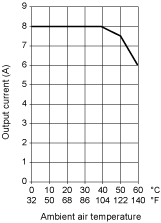
Operating curve:
|
|
140 CPS 424 00
|
48/72 Vdc
|
Operating curve:
|
|
140 CPS 524 00
|
125 Vdc
|
8 A (60°C)
|
Similar to the summable supplies, the Quantum redundant power supplies also contain circuitry which forces the installed power supplies to share output current almost equally. An important difference between the summable and the redundant supply lies in the system POK generation circuitry.
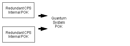
The Quantum system POK signal in systems powered by redundant power supplies is true (power is OK) if either or both internal POK is true.
The following figure shows the Quantum system POK redundant power supply direction:
NOTE: Redundant power supply module health may be monitored in an I/O module health status word.
Another important difference from the summable system is the total available system rack loading. If there are N redundant power supplies installed in a rack, the total rack load must not exceed the capability of N-1 supplies. (Nmax=3)
For example, if two 8 A power supplies are installed in the rack (N=2), the maximum rack load available for redundant operation is the current sourced by N-1 ( = 1) supplies, which is 8 A. If three 8 A redundant power supplies are installed (N = 3), the maximum rack load available for redundant operation is the current sourced by N-1 ( = 2) supplies, which is 16 A.
If these constraints are observed, then in a system of two or three redundant supplies, one supply (it doesn’t matter which one) is hot-swappable. This is possible because there is excess capacity in the N-1 remaining supplies to source the rack current while the Nth supply is being swapped.
An obvious extension to this argument is that a single redundant power supply may be used as a standalone supply (but the cheapest solution is obtained by using a summable or standalone supply for this application).

 CAUTION


