|
Analog Grounding Consideration
|
|
|
Original instructions
|
|
Elements
|
Description
|
|---|---|
|
Side Supports and grounding bar
|
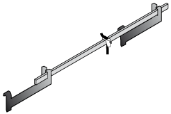
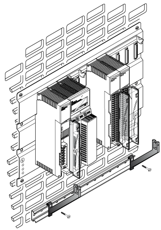
The following illustration describes the assembly of the side supports and the grounding bar.
 |
|
Step
|
Description
|
|---|---|
|
1
|
Push the side supports against the walls and tighten the screws.
 |
|
2
|
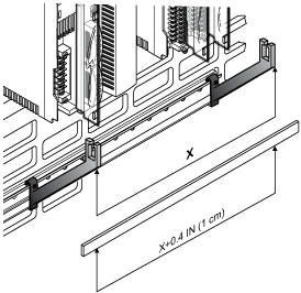
Choose the length of the grounding bar.
 |
|
3
|
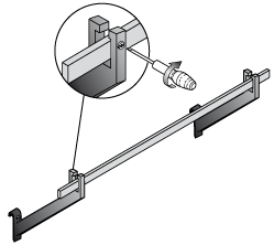
Insert the functional grounding terminal block and tighten the screw
 |
|
4
|
Fix the grounding bar at the side supports.
 |
|
5
|
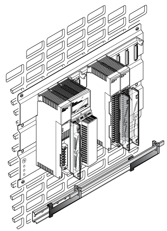
The following figure describes the final assembly of the STB XSP 3000.
 |
|
Reference
|
AWG
|
mm2
|
|---|---|---|
|
STB XSP 3010
|
16 to 9
|
1.5 to 6.5
|
|
STB XSP 3020
|
10 to 7
|
5 to 11
|
