|
|
(Original Document)
|
|
PCMCIA card
|
Slot A (top)
|
Slot B (bottom)
|
|---|---|---|
|
Standard: TSX
MRPP• and MFPP•
|
Yes
|
No
|
|
Application and Files: TSX MRPC• and MCPC•
|
Yes
|
No
|
|
Data or Files:
TSX MRPF•
|
Yes
|
Yes
|
|
Step
|
Action
|
Illustration
|
|---|---|---|
|
1
|
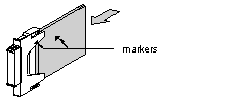
Place the end of the memory card (opposite end to the connector) between the arms of the clip.
The markers (in the form of a triangle) on both the clip and the card label must be facing same way.
|
 |
|
2
|
Slide the memory card into the clip until it stops. The card is now firmly attached to the clip.
|
 |
|
Step
|
Action
|
Illustration
Card with a PV ≤ 03 (1)
|
Illustration
Card with a PV > 03 (1)
|
|---|---|---|---|
|
1
|
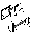
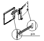
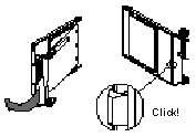
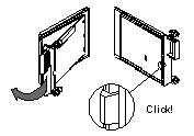
Guide the memory card into the extractor from an oblique angle, placing the 2 pins on the card into the 2 grooves on the extractor.
|
 |
 |
|
2
|
Swivel the extractor on the card until it is fully locked.
|
 |
 |
|
Legend
|
|||
|
(1): the Product Version (PV) is shown on the label affixed to the PCMCIA card.
|
|||
|
Step
|
Action
|
Illustration
Card with a PV ≤ 03 (1)
|
Illustration
Card with a PV > 03 (1)
|
|---|---|---|---|
|
1
|
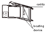
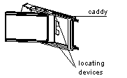
Guide the memory card into the caddy from an oblique angle using the 2 locating devices.
|
 |
 |
|
2
|
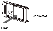
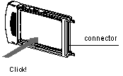
Slide the memory card into the caddy until it stops. The card is now firmly attached to the caddy.
|
 |
 |
|
Legend
|
|||
|
(1): the Product Version (PV) is shown on the label affixed to the PCMCIA card.
|
|||
|
Step
|
Action
|
|---|---|
|
1
|
Remove the protective cover by unlocking it and then pulling it forwards out of the PLC.
|
|
2
|
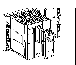
Place the PCMCIA card fitted with its clip (or caddy) into the opened slot. Slide the card-clip assembly in until the card can go no further, then press the clip (or the caddy) to connect the card.
|
