|
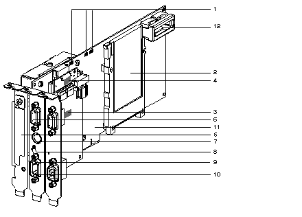
Physical Description of Atrium Processors
|
|
|
(Original Document)
|

|
Number
|
Function
|
|---|---|
|
1
|
RUN, TER, BAT, I/O and FIP indicator LEDs (the FIP LED is only present on the TSX PCI 57 354 model).
|
|
2
|
Slot for a type 1 PCMCIA memory extension card.
|
|
3
|
Micro-switches for coding the rack address on the X Bus.
|
|
4
|
Micro-switches for coding the moduleís position on the rack.
|
|
5
|
Slot for a PCMCIA type 3 communication card.
|
|
6
|
Female 9-pin SUB-D connector used to remote the X Bus to an extendable rack.
|
|
7
|
Terminal port (TER connector (8-pin mini-DIN)): this is used to connect an FTX type or PC compatible terminal, or to connect the PLC to the Uni-Telway bus through the TSX P ACC 01 insulation unit. This connector is used to supply 5V to the peripheral which is linked to it (limited by the available current provided by the PC's power supply).
|
|
8
|
Recessed RESET button which when pressed causes a cold startup.
The RESET button must be pressed using a non-conductive object.
|
|
9
|
ERR LED.
|
|
10
|
Male 9-pin SUB-D connector for linking up to a master Fipio bus. This connector is only present on the TSX PCI 57 354 processor.
|
|
11
|
32-bit PCI connector, used for linking up to the host PC.
|
|
12
|
Slot accommodating a battery for backing up the processorís internal RAM memory.
|