|
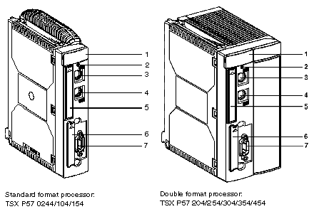
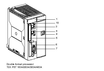
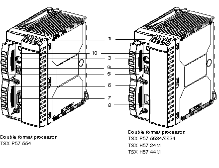
Physical Description of TSX P57/TSX H57 Processors
|
|
|
(Original Document)
|


|
Number
|
Function
|
|---|---|
|
1
|
Display panel containing four or five LEDs.
|
|
2
|
Button for requesting extraction of PCMCIA card and storage of SRAM files.
The button must be pressed before extracting the card, and a LED indicates the status of the request.
|
|
3
|
Terminal port (TER Connector (8-pin mini-DIN)):
this is used to connect an FTX type or PC compatible terminal, or to connect the PLC to the Uni-Telway bus through the TSX P ACC 01 insulation unit. This connector is used to supply 5V to the peripheral which is linked to it (limited by the available current provided by the power supply).
|
|
4
|
Terminal port (AUX Connector (8-pin mini-DIN)):
this is used to connect a peripheral with its own power supply (terminal, operator dialog console or printer (no voltage is supplied to this connector)).
|
|
5
|
Slot for a type 1 PCMCIA memory extension card.
If there is no memory card, this slot is fitted with a cover which must be kept in place in order to protect the slot from dust.
Note: On the card holder, the metallic contact has been removed.
|
|
6
|
Slot for a type 3 PCMCIA communications card which is used to link a Fipway, Fipio Agent, Uni-Telway, serial link, Modbus or Modbus Plus communication channel to the processor.
This slot may also contain a SRAM file storage card (for TSX 57 554\5634\6634\24M\44M only).
If there is no communications card, this slot is fitted with a cover.
PCMCIA communication card isn’t support for TSX H57 24M and 44M
|
|
7
|
9-pin SUB D connector for connecting a Fipio bus master. This connector is present only on TSX P57 •54 processors.
|
|
8
|
RJ 45 connector for Ethernet connection.
|
|
9
|
USB Port.
|
|
10
|
Recessed RESET button which when pressed causes a cold startup.
|