How to set up servo control
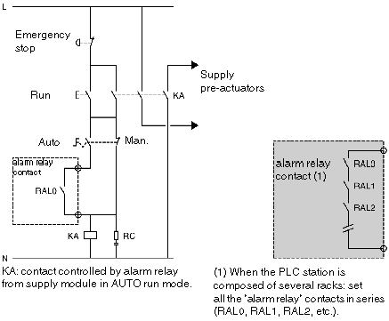
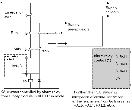
It is recommended that servo control of the different power supplies is set up in the following sequence:
|
Step
|
Action
|
|
1
|
Switch on the power supply to the PLC and the inputs (sensors), using the contactor KM (see diagram). |
|
2
|
If the PLC is in RUN mode and running on AUTO, switch on the output power supply (pre-actuators), using the contactor KA. This is controlled by the alarm relay contact in each power supply.
|
Before restarting the installation following a stop (caused by a power outage or an emergency stop), safety standards require authorization to be given by the operator.
The MANU/AUTO switch makes it possible to force outputs from a terminal, when the PLC is in STOP mode.
PLC station supplied by alternating current:
PLC station supplied by direct current:

