|
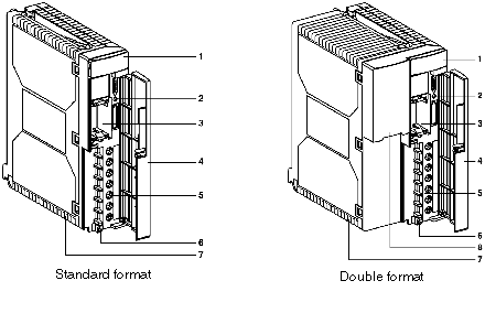
Supply modules: description
|
|
|
(Original Document)
|

|
Number
|
Function
|
|---|---|
|
1
|
Display block containing:
|
|
2
|
Recessed RESET button which, when pushed, triggers a warm restart of the application.
|
|
3
|
Slot for a battery which allows the processorís internal RAM memory to be saved.
|
|
4
|
Flap for protecting the front panel of the module.
|
|
5
|
Screw terminal block for linking up to:
|
|
6
|
Hole for a cable-tightening clip to go through.
|
|
7
|
Fuse located under the module protecting:
Note: on the TSX PSY 2600/5500/5520/8500 supply modules, the primary voltage protection fuse is inside the module and cannot be accessed.
|
|
8
|
110/220 voltage selector, only present on alternating current supply modules TSX PSY 5500/8500. On delivery, the selector is set to 220.
|