|
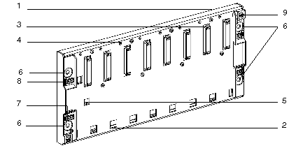
Standard rack: description
|
|
|
(Original Document)
|

|
Number
|
Description
|
|---|---|
|
1
|
Metal sheet which:
|
|
2
|
Holes to be used as anchor-points for module pins.
|
|
3
|
Female 48-pin 1/2 DIN connectors for connecting each module to the rack.
When racks are delivered, these connectors are protected by covers, which must be removed before modules are installed.
The connector on the farthest left marked PS is always dedicated to the rack supply module. The other connectors marked 00 to .. are for receiving all the other module types.
|
|
4
|
Screw-holes for the module-mounting screws.
|
|
5
|
Guide-hole to assist in mounting the supply module.
As supply modules have a projecting part on the back, this module cannot be mounted in any other position.
|
|
6
|
Holes for mounting the rack onto a support. These holes can take M6 screws.
|
|
7
|
Slot to hold the label for the rack address.
|
|
8
|
Slot to hold the label for the station network address.
|
|
9
|
Ground terminals for grounding the rack.
|