Mechanism
Galvanic coupling is a line guided coupling. This phenomenon occurs if shared line sections belong to different circuits. With every change in current in one of the circuits a voltage change is made on the common line so that the circuits influence each other.
Galvanic coupling typically occurs on the following circuits:
Coupling of different circuits to the same power supply
Coupling between operational circuits and grounding circuits (earth circuit coupling)
Coupling different circuits with a common reference conductor system
Example
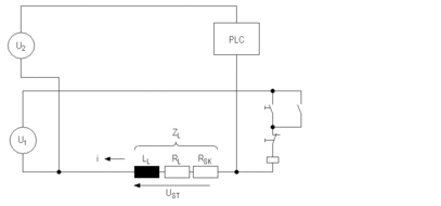
The following circuit diagram shows two circuits with a common reference conductor.

Character definitions
Character |
Meaning |
|---|---|
U1 |
Voltage in circuit 1 |
U2 |
Voltage in circuit 2 |
USt |
Interference voltage |
ZL |
Impedance of the common line from circuits 1 and 2 |
When a circuit is wired as seen in the upper diagram then switching the contact in circuit 1 causes a voltage drop on the common line impedance ZL. This voltage drop overrides the proper signal in circuit 2 as interference.
Size of the interference
The intensity of the interference is determined by the impedance of the common conductor and the size of the change in current.
Voltage drops on a common conductor with a change in current

Character definitions
Character |
Meaning |
|---|---|
I |
Current fluctuation |
USt |
Interference voltage |
LL |
Self inductivity on the common line (frequency dependent) |
RL |
Actual resistance of the common conductor |
RSK |
Additional resistance on the common conductor caused by skin-effect (frequency dependent) |
Actual resistance RL
The Ohmic DC resistance RL is effective for currents with frequencies into the Kilohertz range. Utilizing a broad enough cross-section wire generally cures the problem.
Resistance with skin effect RSK
The resistance increase caused by the skin-effect basically rises according to the following formula

Character definitions
Character |
Meaning |
|---|---|
K |
Geometry factor (less with larger conductive surface) |
f |
Interference frequency |
Line inductivity LL
The self inductance LL depends on the line geometry and the distance to the ground environment and can be reduced by a factor of 10 by a conductor with a broader surface area. With standard signal lines and wiring, it has approximately the value:

Influence of line geometry
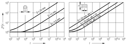
The effects of line geometry on the frequency dependent effective resistance R are shown in the following diagram. The diagram on the left shows the dependence for a conductor with a round cross section and the one on the right shows the same for a conductor with a rectangular cross section.

R Effective resistance
R0 D.C. resistance


