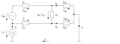
Common mode-differential mode-conversion
When the impedance of the lines is uneven or if stray capacitances are found, a common mode-differential mode-conversion occurs. The asymmetrical ratios then create a differential voltage which is then carried with the useful signal.
Circuit diagram of common mode-differential mode-conversion with stray impedances ZSt between the circuit and reference ground as well as with different line impedances ZL.

Character definitions
Character |
Meaning |
|---|---|
UN |
Useful voltage |
US |
Interference voltage at the source interference |
US’ |
The signal voltage is overridden by the interference voltage; this part is brought about by the common mode-differential mode-conversion |
Z |
Impedance (e.g. in measurement device) |
ZL 1,2 |
Different line impedance in lines 1 and 2 |
ZSt 1,2 |
Stray impedances |
IS |
Interference current |
IS1,2 |
Partial current in both branches of the electrical circuit |


