Overview
This section describes how to provide two types of grounding for assembled Momentum devices:
functional earth (FE), used to discharge high frequency disturbances, guaranteeing proper EMC behavior
protective earth (PE), used to protect against personal injuries according to IEC and VDE
Grounding Momentum Devices
Momentum devices consist of an I/O base assembled with a communications adapter or a processor adapter and possibly an option adapter. The PE of the adapters is electrically connected with the PE of the I/O base; you do not have to provide any further grounding of the adapter.
Grounding Guidelines
Follow these guidelines.
Be sure you establish good ground contacts.
Connect the grounding screw to protective earth (PE) for AC and DC modules with a recommended maximum torque of 4.4 in/lb (0.5 Nm) using a PZ2 driver.
Cable Specifications
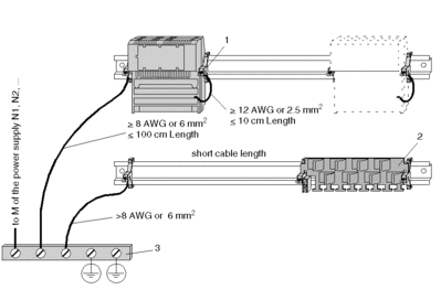
When you are using ground cable up to 10 cm (4 in) long, its diameter should be at least 12 AWG (or 2.5 mm2). When longer cables are used, larger cable diameters are required, as shown in the following illustration.
Grounding Scheme
The illustration below illustrates properly grounding modules and tracks.

1 grounding clamp, such as EDS 000
2 cable grounding rail (CER 001), an optional component for grounding lines close to PE/FE rail
3 PE/FE rail in the cabinet or PE/FE screw in terminal cabinet


