Overview
This section discusses specific cases when inductive loads at output points require additional protective circuits (directly on the actuator) and provides two examples of protective circuitry.
Case 1
When there are contacted circuit elements (e.g. for safety interlocks) in the output conductors.
Case 2
When the leads are very long.
Case 3
Where inductive actuators are operated via relay contacts of the I/O base (to extend contact life and for EMC considerations).
Protective Circuit Types
In all three cases, the protective circuit is a clamping diode.
The following table provides generic selection guidelines.
Type of Load |
Suppression Device |
Minimum Component Rating |
|
|---|---|---|---|
DC circuits |
a reverse-biased clamping diode across the load |
2 A and greater than twice the maximum load voltage |
|
Consult relay and contactor manufacturers’ catalogs for commercial suppression devices matched to your particular products.
Example 1
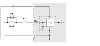
An example of a protective circuit for inductive DC actuators is illustrated below:

K1 contact, e.g., for safety interlocks
V1 clamping diode as the protective circuit
Example 2
Another example of a protective circuit for inductive DC actuators is illustrated below:

V2 clamping diode as the protective circuit


