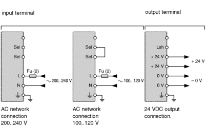
Illustration 1
Normal connection diagram:

Illustration 2
Parallel connection diagram (parallelization):

(1) Connection for a 100...120 VAC power supply.
(2) External fuse on phase (Fu): 250 V 6.3 A time delay.
Connection rules
Primary: Observe the rules concerning phase and neutral when wiring.
an operating voltage ≥ 600 VAC with a cross-section of 1.5 mm2 (14 AWG) or 2.5 mm2 (12 AWG) for connection to the mains,
| DANGER | |
|---|---|
The power supply terminal is protected by a flap which allows access to the wiring terminals. The wires come vertically out of the power supply at its base. These wires can be kept in place with a cable-clip.
Secondary: To comply with isolation requirements (EN 60950) for a 24 V SELV isolated voltage, the following wiring is used:
an operating voltage ≥ 300 VAC with a cross-section of 2.5 mm2 (12 AWG) for the 24 V outputs and the ground.
Wire the two 24 V terminals in parallel, or distribute the load over the two 24 V outputs when the total current to be supplied is greater than 5 A.


